14
15
www.LCDracks.com
Marshall Electronics
VSW-2200 Operation Manual
Menu Settings
Compatible files:
- BMP or PNG format
- 1080 x 1920, 1280 x 720, 576 x 720, 576 x 704,
or 720 x 480 , 640 x 480, 800 x 480 pixels (horizontal pixels divisible by 128)
- 256-bit color or lower
Click on the Update button to start the file transfer.
15. Firmware Update button
Use this function to update the features of the VSW-2200 switcher.
Please consult the instructions included with the update files for details.
Firmware updates are made available on the Marshall Electronics website at:
http://www.lcdracks.com/Switchers/index.php
16. Connected button
When the VSW-2200 switcher is properly connected to a computer, either via USB or Ethernet,
the Connected button will appear as highlighted in green. Clicking on this button will toggle the
connection between the computer and switcher on and off. Clicking again will reestablish the
connection as long as neither device (switcher or computer) has been turned off or unplugged.
17. Refresh button
In the rare case where the control application does not indicate selections made on the switcher
panel, clicking the Refresh button will re-synchronize the application with the switcher.
18. Information button
In the rare case where the control application does not indicate selections made on the switcher
panel, clicking the Refresh button will re-synchronize the application with the switcher.
19. Factory Reset button
Please use this function with care. Once this button is clicked, the reset function will run until it is
complete. The reset process takes about 25 – 30 seconds. The switcher will turn off and turn back
on during this process which means that Program Output will go off and back on.
When using the Factory Reset, the settings in the switcher will be set back to their default state.
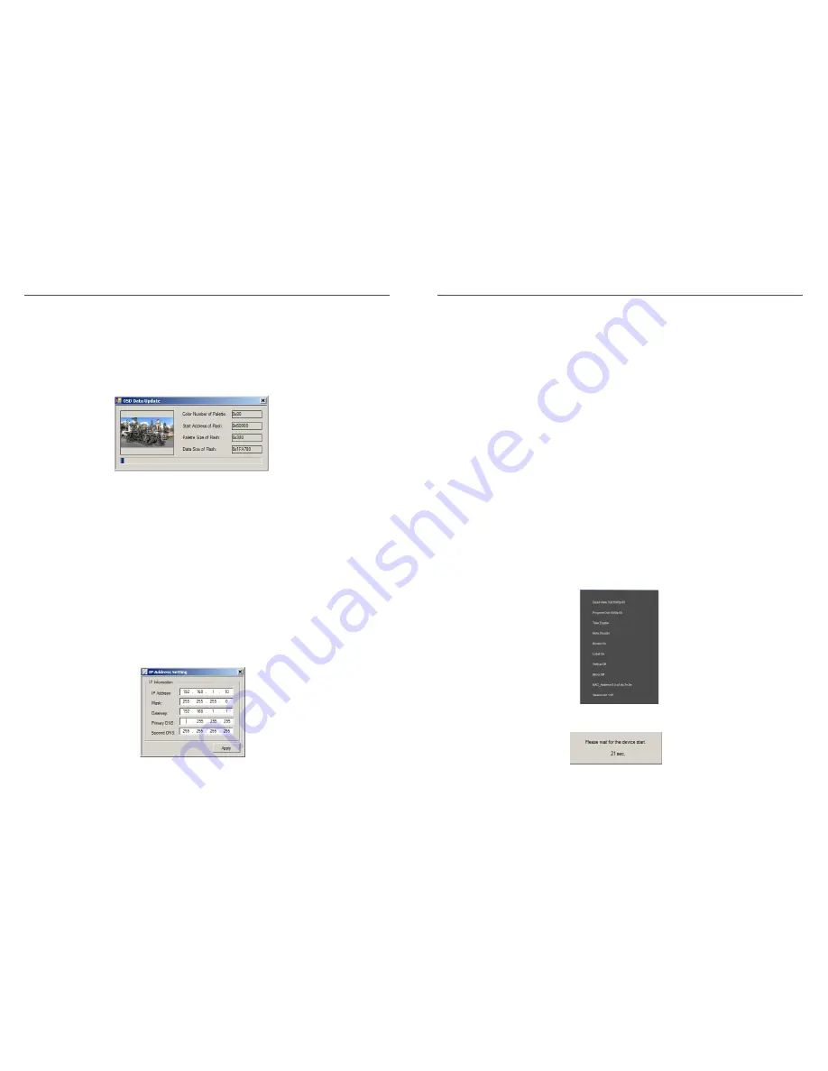
The progress bar will show the current status of the file transfer. Please allow the transfer to
complete before closing the window.
13. Port Setting button
The Port Setting button brings up the window that appears when the switcher is first turned on.
Please see the sections on USB and Ethernet connections for details. These settings are used to
select the way the switcher is controlled from a computer.
14. IP Setting button
Use this function to change the switcher’s IP address, Subnet mask or Gateway settings for use
on an Ethernet network. Simply type in the desired parameters and click the Apply button. The
switcher will respond by briefly recycling. Keep in mind that no matter what address is assigned
here, even when a mistake is made, control can be regained and reconfigured using the direct
USB connection.


