Marshall Electronics V-R261-DLW Operating Instructions Manual Download Page 31

31

SERVICE SUBMENU

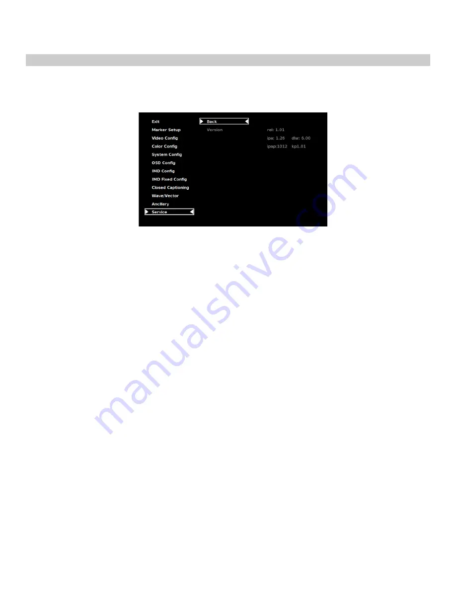
Software Version Display

The Main Board, Keypad, and FPGA software version numbers are displayed.

.

The following information is displayed:

• rel:

Release Package version number

• ipa

Input processor firmware

• dlw

FPGA Version

• ipap

Product Type

• kp

Keypad version number

Service Menu

Summary of Contents for V-R261-DLW

Page 1: ...Marshall Electronics Model No V R261 DLW 26 Full Resolution Dual Link Waveform Monitor Operating Instructions...

Page 2: ...2 This page intentionally left blank...

Page 3: ...hrome Mode 15 Blue Only Mode 15 Pixel to Pixel Mode 16 Aspect Ratio Settings 16 Curtain Color 17 Ctemp Gamma 17 Analog Phase 17 DVI A CSC Mode 17 DVI D CSC Mode 17 HDMI CSC Auto 18 Color Configuration...

Page 4: ...ity to view the Waveform monitor Vectorscope SDI Link status and Video individually Closed Captioning Decoding The DLW monitor allows for decoding of Closed Captioning in the EIA 608 or EIA 708 In Mon...

Page 5: ...with a desktop stand for desktop use Marshall Part V ST23 32 VESA standard 75mm hole patterns allows custom mounting installations Marshall Electronics can provide an optional VESA stand with pivot an...

Page 6: ...will light User Definable Function Buttons Four user definable function buttons can be used for direct access to various settings Functions are assigned using the on screen menu Layout Button Use thi...

Page 7: ...should be supplied ot the HD 15 port 3G SDI Inputs and Outputs The V R261 DLW has two 3G SDI inputs and two active loop through outputs SDI 1 and SDI 2 can be used simultaneously to display Dual Link...

Page 8: ...25 24 23 98 1080psF 30 29 97 25 24 23 98 The following Dual Link standards are supported by the V R261 DLW YCbCr 4 2 2 1080p 60 59 94 50 YCbCr RGB 4 4 4 4 2 2 10 Bit 12 Bit 1080i 60 59 94 50 1080p 30...

Page 9: ...R261 DLW has 4 possible layouts Multi mode Vectorscope mode Waveform mode and Full Screen Video mode Each press of the LAYOUT Button will change the current mode to next available mode Default Multi m...

Page 10: ...10 Waveform Monitor Mode Full Screen Video Mode...

Page 11: ...11 On Screen Menu STRUCTURE OVERVIEW...

Page 12: ...main menu or each submenu Press the RotoMenu knob to enter a submenu or choose a setting To return to main menu from submenu select Back and press the RotoMenu The menu timeout can be set in the OSD...

Page 13: ...95 Safe Area 93 Safe Area 90 Safe Area 88 Safe Area 80 Safe Area 1 85 1 Aspect Ratio 2 35 1 Aspect Ratio 4 3 Aspect Ratio 14 9 Aspect Ratio 13 9 Aspect Ratio 16 9 Marker Examples 4 3 Markers Use this...

Page 14: ...imposed on the complete image 50 Gray Screen area beyond the marker is shown at 50 intensity Black Screen area beyond the marker is shown as black Example 80 Marker in 4 3 Mode Center Marker Use this...

Page 15: ...bars with the following procedure 1 Allow the monitor to warm up for at least 5 10 minutes 2 Display SMPTE split field color bars on the monitor using an external source 3 Enable Monochrome mode 4 Lo...

Page 16: ...m 4 3 portion of the screen 1600 x 1200 IMD text and time code are superimposed on the lower portion of the image The audio presence indicator and on screen tally are displayed at the bottom of the sc...

Page 17: ...es of colorspace inputs This setting will only affect your DVI A inputs RGB Studio accommodates digital 480i video using the RGB limited range 16 235 inputs RGB PC accommodates full range RGB 0 255 in...

Page 18: ...ve will determine the colorspace configuration Color Config Submenu Use the Color Configuration submenu to adjust the Red Green and Blue Offset and Gain values of the two SDI channels the DVI D input...

Page 19: ...its option of the Waveform Monitor On or Off Aspect Ratio Toggle between 4 3 and 16 9 aspect ratios Pixel to Pixel Enable disable Pixel to Pixel mode Ctemp Gamma Rotate amongst color temperature setti...

Page 20: ...remote IMD text commands Status Display Use this setting to enable or disable status display When enabled the current video input standard is displayed on the top left of the screen When disabled sta...

Page 21: ...bottom left of the screen and red is shown at the bottom right The following diagrams show RGY RG and GR OSD Tally modes When the Tally Source is set to TSL MEI 422 OSD Tally can be set to Off or IMD...

Page 22: ...will flash on the icon if no embedded audio is present CC Monitor Closed Captioning Use the CC Monitor menu option to enable or disable the Closed Captioning presence indicator icon When enabled this...

Page 23: ...creen to the controlling device When using the TSL protocol the ID of each screen should be manually set in conjunction with the controlling device When using the Image Video protocol the ID may be se...

Page 24: ...ally interface Image Video HW Use the Image Video HW setting to control Image Video tally states via contact closure on the HD 15 tally interface Contact closure of the Red pin corresponds to Image Vi...

Page 25: ...ach name can be up to 16 ASCII characters Press RotoMenu knob to edit the IMD Name Rotate the RotoMenu knob to move the cursor Press the RotoMenu knob with the cursor on the character to be changed th...

Page 26: ...cates an unused NULL value in the string The string entered will be terminated by the first Characters to the right of a character will be displayed in the menu but will not be shown in the IMD string...

Page 27: ...tor Submenu Use the Wave Vector submenu to change the location of the Waveform Monitor and Vectorscope as well as the data displayed on the Waveform monitor or the Vectorscope on the V R261 DLW monito...

Page 28: ...in Green and B shown in Blue components of the signal are displayed from left to right RGB Overlay The RGB components of the signal are overlaid Waveform Scale Use the Waveform scale option to switch...

Page 29: ...Use this to set the desired minimum for the Limit display of the waveform monitor Any Waveform data that goes below this Limit Max will be displayed in red Vectorscope Targets Use the Vectorscope Tar...

Page 30: ...should be counted on the DLW monitor display For example 0x6060 would count the Timecode data packets 0x6101 would count the EIA 708 CC data packets and 0x6102 would count the EIA 608 CC data packets...

Page 31: ...he Main Board Keypad and FPGA software version numbers are displayed The following information is displayed rel Release Package version number ipa Input processor firmware dlw FPGA Version ipap Produc...

Page 32: ...Y HARDWARE INTERFACE HD 15 Activation requires contact closure of pin to ground on the HD 15 connector Pin No Signal 1 Channel 1 Green 2 Channel 1 Red 3 Channel 1 Yellow 4 Ground 5 Ground 6 N C 7 N C...

Page 33: ...33 Dimensions...

Page 34: ...If there is no proof of purchase provided with a warranty claim Marshall Electronics reserves the right not to honor the warranty set forth above Therefore labor and parts may be charged to the consu...

Page 35: ...35 This page intentionally left blank...

Page 36: ...36 Marshall Electronics Inc 1910 East Maple Ave El Segundo CA 90245 Tel 800 800 6608 310 333 0606 Fax 310 333 0688 www LCDRacks com sales lcdracks com 2010 0722...

Reviews: