background image

Specifications

Screen Size

7” Diagonal

Display Area (h x v)

6” x 3.6”

Aspect Ratio

16:10 (16:9 / 4:3 Selectable)

Pixels

800 x 480

Color Depth

8-bit (16.7M Colors)

Viewing Angle (h x v)

-55

°

~+65° x -40° ~+50° (CR >10)

Brightness

350 cd/m2

Contrast Ratio

400:1

Pixel Pitch (h x v)

0.1905 x 0.1905 mm

Dimensions (w x h x d)

18.9” x  5.2” x  2.4”

Weight (Monitor Only)

6 lbs including power adapter

Operating Temperature

32° F to 104° F (0° C to 40° C)

Storage Temperature

-4° F to104° F (-20° C to 40° C)

RoHs

Do not dispose. Return to 

Manufacturer or Authorized 

Recycle Facility.

■  

PANEL

■  

VIDEO INPUT/OUTPUT

HD/SD-SDI Video Input / Output

■  

AUDIO INPUT/OUTPUT

Up to 16 channels of audio de-embedded from the SDI signal

Dual Headphone outputs on Front Panel

3.5mm -10dBu Un-Balanced output on rear panel

Stereo 3-pin XLR Ba4dBu Line Output on rear panel

■  

CONNECTORS

Video Input

 - 2 x BNC Female (75 Ω)

Video Output (Active Loop-Through)

 - 1 x BNC Female (75 Ω)

Parallel Remote

 - RJ-45

Optional Input Slot

Audio Output Jacks: 

Front  3.5mm Stereo Headphone

Front  ¼” Stereo Headphone

Rear 

XLR Bal +4 Stereo Line Output 

Rear 

3.5mm -10 Un-Balanced Line Output

Service Terminal  

Power Input

: 4-Pin Male XLR


Pin 1:  GND


Pin 2:  N/C


Pin 3:  N/C

  Pin 

4: 

+12VDC

■  

ELECTRICAL

Power Consumption

 - 2 Amp (Max) @ 12VDC (24W Max)

Voltage Requirement 

- 12VDC (10VDC-18VDC)

■  

MECHANICAL

22

23

Maintenance / Color Calibration / Upgrade Procedure

■  

Screen Cleaning

Periodically clean the screen surface using ammonia-free cleaning wipes (Marshall Part No. V-HWP-K). 

A clean micro-fiber cloth can also be used using only non-abrasive and ammonia-free cleaning agents. 

Do not use paper towels. Paper towel fibers are coarse and may scratch the surface of the polycarbonate 

faceplate or leave streaks on the surface. Antistatic and fingerprint resistant cleaning agents are recommended. 

Do not apply excessive pressure to the screen to avoid damaging the LCD.

■  

Faceplate Dusting

Dust the unit with a soft, damp cloth or chamois. Dry or abrasive cloths may cause electrostatic charge on the 

surface, attracting dust particles. Neutralize static electricity effects by using the recommended cleaning and 

polishing practice.

■  

Color Calibration Procedure

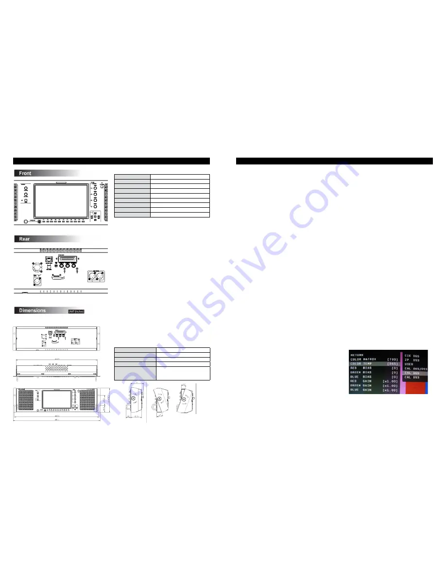
*** In order to perform color calibration an optional OR-SM Service Module is required. ***

•  Allow both the unit you want to calibrate and the Minolta® CA-210 to warm up for a minimum of 20 minutes.

•  Attach the CA-210 color probe to the update dongle.

•  With the unit still turned on, insert the update dongle into the service port at the rear of the screen you wish to 

calibrate.

•  Use the menu navigation joystick or menu buttons of the appropriate screen and go to:


 Color Menu Color Temp 

• Cal D65/D93 to calibrate both 

• Cal D65 to calibrate only D65 

• Cal D93 to calibrate only D93

Press enter once to select and again to confirm

•  Follow the on-screen instructions

Notes: 
1. If there is no color probe attached or you make a mistake and try to calibrate the incorrect screen, you will get an error message and 
the screen will default to previous settings.
2. If the calibration process is interrupted while in progress, the current screen settings will be corrupted and the calibration process 
will have to be repeated.

■  

Upgrading Orchid Firmware

*** In order to install new firmware an optional OR-SM Service Module is required. ***

Procedure: 

  1. Download the Orchid update software package from the Marshall web site  

  2. Unzip the included files from the zip folder to a known location on your computer 

  3. Double-click the Un-Zipped Orchid Update program and firmware package to install on your computer  

  4. Turn on the Orchid unit to be upgraded 

  5. Connect the OR-SM module to your computer 

  6. Insert the OR-SM module into the Service port 

  7. Run the Orchid Update program 

  8. Click Update 

•  The Updater will check for available software 

•  Compare it to the current version 

•  Perform the update.

Notes: 

•  

The update process will take approximately 8 minutes.

•  

If the Update program does not automatically detect your Orchid model you will be asked to choose the appropriate model from a    

    drop down list then click Update again.

•  

Clicking on Details allows you to monitor the update process

Summary of Contents for ORCHID OR-701A

Page 1: ...OR 701A 7 0 Full Featured Rack Mount Audio Video Monitor System Operating Instructions Marshall Electronics ...

Page 2: ...eeds The OR 701A is equipped with two HD SD SDI inputs with an active switched loop thru as well as optional input slot which can be used for and additional Component DVI I or other input formats Diagnostic tools include our exclusive ClipGuide feature 16 Tri ColorAudio Bar Graph meters with peak hold and numeric display of headroom and peak levels as well as real time analysis of color space conv...

Page 3: ...ne 3 5mm On the rear panel there is a stereo 4 line output using 3 pin XLR connectors and a 3 5mm 10 unbalanced jack to feed an external amplifier It is possible to utilize both the front panel Headphone Connectors and rear panel line output connectors simultaneously with individual volume controls Precision Audio Level Meters De embeds and displays up to 16 channels of audio using sixteen 64 segm...

Page 4: ...he push button at the bottom mutes the front speakers only When muted the led indicator turns RED Insertion of a headphone plug into either the or 3 5mm headphone jacks will not mute the front speakers The Front speakers are not affected by the Audio Mute command found in the Function Preset menu 1 2 3 4 5 6 Front Panel Features 6 1 4 5 6 3 2 7 7 Rear Panel Features Parallel Remote RJ 45 Pin Assig...

Page 5: ...ibrated setting GAMMA 1 0 to 3 0 in 0 1 steps 2 2 is Calibrated Setting COLOR RETURN COLOR MATRIX AUTO RGB BT 601 BT 709 COLOR TEMP CIE D65 JP D93 USER CAL D65 D93 CAL D65 CAL D93 RED BIAS 128 to 127 0 is Calibrated Setting GREEN BIAS 128 to 127 0 is Calibrated Setting BLUE BIAS 128 to 127 0 is Calibrated Setting RED GAIN 0 500 to 1 992 x1 00 is Calibrated setting GREEN GAIN 0 500 to 1 992 x1 00 i...

Page 6: ...ROMA C CHROMA C ON MONO Y C Y C ON MONO DISPLAY TYPE ZEBRA FILL Y UPPER LIMIT 100 0 IRE 7 3 to 109 1 Y LOWER LIMIT 0 0 IRE 7 3 to 109 1 C UPPER LIMIT 0 255 016 7 5 IRE 235 100 IRE C LOWER LIMIT 0 255 016 7 5 IRE 235 100 IRE USER ASSIGN RETURN F 1 THRU F 5 INPUT 1 INPUT 2 INPUT 3 GAMMA 1 0 GAMMA 1 8 GAMMA 2 0 GAMMA 2 2 GAMMA 2 4 GAMMA 2 6 WHITEBALANCE D65 WHITEBALANCE D93 MONO On Screen Menu contin...

Page 7: ...rms to CIE D65 White Point x 0 3127 y 0 3290 D93 9300K Conforms to Japanese D93 White Point x 0 2830 y 0 2980 USER Adjustable Color Bias and Gain CAL D65 D93 CAL D65 CAL D93 RGB Bias and Gain Select this submenu to fine tune the monitor s color balance R G B This should only be done by someone experi enced with video engineering as this will alter the overall color shading of the screen The purpos...

Page 8: ...e with 16 9 source or native 4 3 in AUTO mode H V Delay Use this setting to enable H V Delay In H V Delay mode both horizontal sync and vertical sync are delayed resulting in both horizontal and vertical blanking periods being shown at the center of the screen Shift H Use the Up éand Down ê menu buttons to change the value of this setting will shift the picture Horizontally Negative values will mo...

Page 9: ...no feed Load CH Preset From Use this menu to recall one of the 8 possible memory locations where the user previously stored channel output assignments Use of this Load command will override the current channel output assignments AUDIO CONFIGURATION SUBMENU 16 Save CH Preset To Use this menu to select which one of 8 memory locations where the user wants to store the current channel output assignmen...

Page 10: ...r conditions are indicated by a solid fill In either Zebra or Fill mode Red is the indication for Luma and Yellow is the indication for Chroma Y Limits These values are shared with WFM settings Set luminance upper and lower limits to be monitored Limits are displayed in IRE unit Varies between 7 3 IRE and 109 1 IRE This value will be shown in WFM window as red line Any data exceeding these values ...

Page 11: ...cases the value of LTC and VITC1 will be identical to each other Power Save When enabled the monitor will go to sleep after a predefined time has passed when loss of picture occurs When a valid video format is detected the monitor will wake up from the sleep state Pressing any front panel keys will wake up the monitor In the sleep state all lights including the backlight and front key indicators a...

Page 12: ...ause electrostatic charge on the surface attracting dust particles Neutralize static electricity effects by using the recommended cleaning and polishing practice Color Calibration Procedure In order to perform color calibration an optional OR SM Service Module is required Allow both the unit you want to calibrate and the Minolta CA 210 to warm up for a minimum of 20 minutes Attach the CA 210 color...

Page 13: ...ns or modifications in design or construction void this warranty It is considered normal for a mini mal amount of pixels not to exceed three to fail on the periphery of the display active viewing area Marshall Electronics reserves the option to refuse service for display pixel failure if deemed unobtrusive to effective use of the monitor by our technicians No sales personnel of the seller or any o...

Reviews: