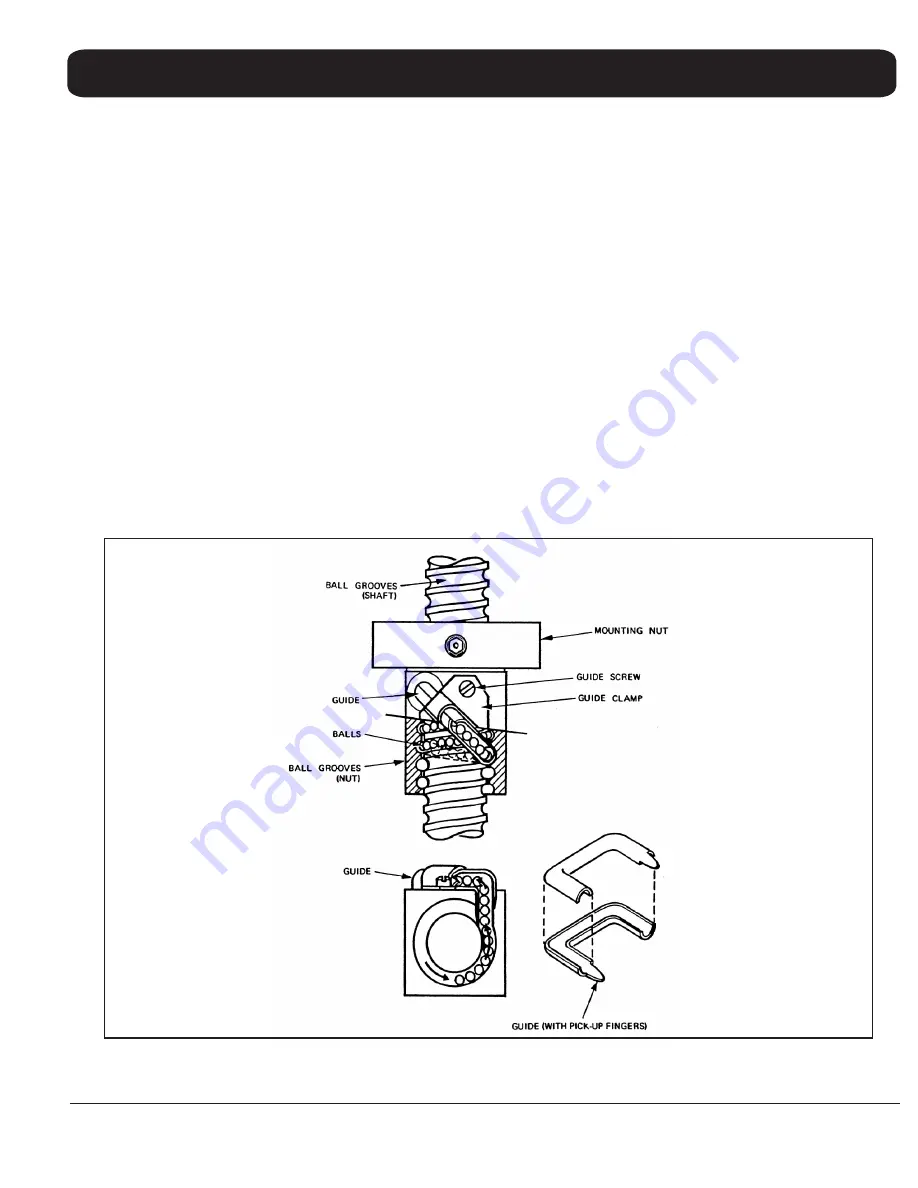
Figure 3-2
Ball Nut Assembly
3-3
Form No. S-2110 08/03
Printed in U.S.A
.
SECTION 3 maintenance
1. Remove the two bolts (8) which hold the ball nut
assembly in the screw lever (7).
2. Remove the two 5/16" hex head cap screws (13)
which fasten the screw housing (14) to the cabinet frame
(not shown).
3. Lift screw assembly from the cabinet.
Proceed in reverse order to replace the assembly.
3.3.5.2 General Inspection and Cleaning:
The screw
assembly should run smoothly throughout the entire
stroke. If operation is not uniform remove the screw
assembly (paragraph 3.3.5.1) and proceed as follows:
1. Inspect screw shaft for signs of accumulation of foreign
matter in the ball grooves.
2. Using cleaning fluid or solvent remove dirt from ball
grooves. Be sure to flush the ball nut assembly
thoroughly.
3. Cycle the ball nut along the screw shaft several times.
Wipe with a dry lintless cloth and lubricate
immediately. (See lubrication 3.2.2).
4. If assembly continues to operate erratically after
cleaning disassemble and inspect the ball nut
assembly.
3.3.5.3 Ball Nut Disassembly:
The Saginaw Screw is a
ball bearing screw power transmission device which
converts the turning motion applied by the hand crank (
1) into bi-directional force against the screw lever (7).
The frictionless "easy" transfer results from the use of
bearing balls circulated be- tween the screw and nut in
concave helical grooves. As the screw rotates inside the
nut, the bearing balls are directed from one end and
carried by a ball guide to the opposite end of the ball nut.
Figure 3-2 shows a cut-away view of the ball nut.


