background image

8

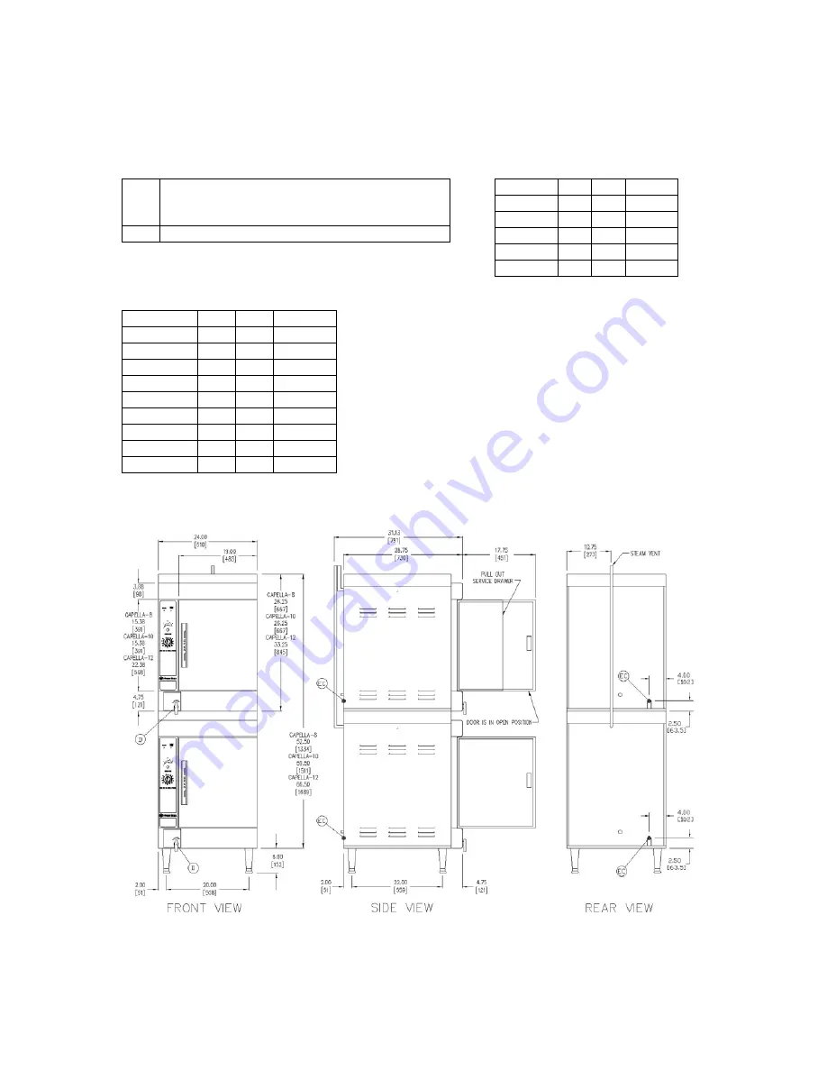
SERVICE CONNECTIONS

(continued)

Models: Capella – 8, Capella – 10 & Capella – 12

Capella Service Connections:

ELECTRICAL (Capella - 4) 60 Hz

EC

Electrical Connection – 1 1/8” knock-out hole
for electrical connection. Rating provided on
data label.

D

Drain – A 6 ft. removable drain hose

Voltage

pH

kW

Amps

208

1

8

39

240

1

8

33

208

3

8

22

240

3

8

19

480

3

7.2

9

ELECTRICAL (Capella - 6) 60 Hz

Voltage

pH

kW

Amps

208

1

8

38.5

240

1

8

33.3

208

3

8

22.2

240

3

8

19.3

208

1

9.8

47

240

1

9.8

41

208

3

9.8

27

240

3

9.8

24

480

3

9

12

NOTES:

4” clearance left mandatory, right and rear is recommended.

Location near a floor drain is recommended.

Steamer sizes can be mix matched. Two 4-pan (Capella-4)

stacked together makes an 8-pan steamer (Capella-8), a 4-
pan and 6-pan (Capella-4 & -6) stacked together makes a 10-
pan steamer (Capella-10), and two 6-pans (Capella-6)
stacked together makes a 12-pan steamer (Capella-12).

Refer to the electrical charts (above and to the left) for proper

voltage requirements for each steamer.

Each compartment, stacked or single, requires a separate

electrical connection.

Summary of Contents for CAPELLA - 10

Page 1: ...4 CAPELLA 8 CAPELLA 6 CAPELLA 10 CAPELLA 12 INSTALLATION OPERATION MAINTENANCE STEAM COOKING GUIDELINES PARTS LISTS PARTS SERVICE 35 Garvey Street Everett MA 02149 Tel 617 387 4100 Fax 617 387 4458 custserv mfii com www mfii com 1 2012 5 9 250 12 6 ...

Page 2: ...Typical foods 14 D Tips on cooking frozen product 14 E Blanching 14 F Tips on pan use 14 G Other helpful hints 15 H WARINGS AND CAUTIONS 15 A Warnings 15 B Cautions 16 I WIRING DIAGRAMS 17 A 208 240 Volts 17 Figure 1 17 B 480 Volts 18 Figure 2 18 J ILLUSTRATED PARTS LIST 19 1 Cabinet assembly 19 Figure 3 19 Figure 4 19 Figure 5 20 Figure 6 20 2 Door assembly 21 Figure 7 21 Figure 8 21 3 General as...

Page 3: ...y before installing or servicing this equipment WARNING Never spray water into electrical components WARNING Do not store or use gasoline or other flammable vapors or liquids in the vicinity of this or any other appliance WARNING Please make certain that every operator of this piece of equipment has been instructed on its proper and safe use and has read and understands all warnings cautions and n...

Page 4: ...he thermostat controller has a built in diagnostic feature that will automatically shut down all heaters if the sensor probe fails which will avoid overheating b Low water shutoff In the event of a low water condition the Add Water indicator light on the control panel will light up If the steamer is not refilled within one minute the steamer will shut down c High Limit shutoff If the steamer runs ...

Page 5: ...ent Directory of Authorized Service Agencies may be obtained by contacting Market Forge Industries Inc 35 Garvey Street Everett Massachusetts 02149 4403 Telephone 617 387 4100 Toll Free 866 698 3188 Fax 617 387 4458 Outside MA Fax 800 227 2659 Parts Price Service Telephone 888 259 7076 Email custserv mfii com Web Site www mfii com ...

Page 6: ... Voltage pH kW Amps 208 1 8 39 240 1 8 33 208 3 8 22 240 3 8 19 480 3 7 2 9 ELECTRICAL Capella 6 60 Hz Voltage pH kW Amps 208 1 8 38 5 240 1 8 33 3 208 3 8 22 2 240 3 8 19 3 208 1 9 8 47 240 1 9 8 41 208 3 9 8 27 240 3 9 8 24 480 3 9 12 NOTES 4 clearance left mandatory right and rear is recommended Location near a floor drain is recommended Refer to the electrical charts above and to the left for ...

Page 7: ... 2 240 3 8 19 3 208 1 9 8 47 240 1 9 8 41 208 3 9 8 27 240 3 9 8 24 480 3 9 12 NOTES 4 clearance left mandatory right and rear is recommended Location near a floor drain is recommended Steamer sizes can be mix matched Two 4 pan Capella 4 stacked together makes an 8 pan steamer Capella 8 a 4 pan and 6 pan Capella 4 6 stacked together makes a 10 pan steamer Capella 10 and two 6 pans Capella 6 stacke...

Page 8: ...set 8 Electrical Diagrams The electrical diagrams are located on the inside of the left side access panel 9 Recommended water quality This steamer does not require filtered water However it is important to properly drain and clean your water reservoir at least daily see 6 0 Cleaning Guidelines in this manual 10 Ball valve drain Drain is activated by a manual ball valve on the lower left front of t...

Page 9: ... door to allow it to cool and complete draining the cooking chamber If draining into a bucket remember that the cooking chamber can hold 2 gallons of hot water E OPERATION 1 Electrical Connection Make sure unit is plugged into a proper receptacle or wired properly and the breaker for the circuit is on 2 Add water Make sure drain valve is in the CLOSE position Pour 2 gallons of water into the cooki...

Page 10: ...x 1 8 12 12 x 20 x 2 4 6 12 x 20 x 4 2 4 The Capella steamer accommodates 4 and 6 deep pans However for best steam cooking performance 1 or 2 deep pans work best Other combinations of these pan sizes will fit in your steamer The steamer will accommodate gastronorm pans 9 Cooking When ready to cook turn the cooking mode selector dial to the desired setting Setting Temperature Use for 1 180 Green ve...

Page 11: ...ray vinegar directly on the mineral build up using a spray bottle For heavy mineral deposits pour two cups of vinegar in the cooking chamber fill to above the water level sensor probe with water and turn the steamer on for 20 minutes Turn the steamer off and leave the door open Allow to soak for several hours Loosen mineral deposits with a nylon bristled brush Drain wipe and rinse with clean water...

Page 12: ...be necessary to add water before the hour is complete If this is the case add water return to steaming temperature and continue steaming until a total of one hour steaming has been reached Turn the unit off and allow it to cool for one hour Drain the unit and rinse the entire cooking cavity thoroughly If the unit is heavily scaled it may be necessary to repeat the process To reorder Stellar Descal...

Page 13: ...frozen vegetables or product if possible c If product is an ice block set it in the pan on its narrowest side This allows the steam to contact a greater surface area d Thawing is faster and better for the food in atmospheric steaming e Make sure frozen product is uniform in size to get best results f Season vegetables AFTER steaming g Less seasoning is required because steaming preserves natural f...

Page 14: ... load more than the rack is designed for Maximum capacity loads cook best with perforated pans d Loosely packed pans will cook faster than tightly packed pans e To skin tomatoes oranges etc more easily steam for a short time then chill in cold water f When steaming pasta shrimp or ground meat nesting a perforated pan in a solid pan works well Lift out the perforated pan to drain g Never have the w...

Page 15: ... stainless steel casing may occur b The steamer must be level in order for the water sensor to function properly c Do not use any abrasive cleaners utensils or scrubbers on the non stick coating this will damage the coating Use vinegar and water to clean reservoir Nylon bristle brushes or soft sponges are recommended d Do not manually refill hot dry reservoir with cold water Damage to the interior...

Page 16: ...17 I WIRING DIAGRAM 1 208 240 Volts Figure 1 ...

Page 17: ...18 2 480 Volts Figure 2 ...

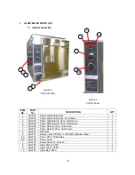
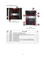
Page 18: ...de 4 Pan Not Shown 1 2 92 0728 Panel Right Side 6 Pan Not Shown 1 3 92 0008 Panel Rear 4 Pan Not Shown 1 3 92 0357 Panel Rear 6 Pan Not Shown 1 4 92 0213 Ball Valve 1 5 92 0721 Washer Flat 7 8 ID x 1 3 8 OD Stainless Steel 1 6a 92 0137 Timer 240V 60 Minutes 1 6b 92 0138 Timer Knob 1 7 92 0125 Rotary Switch 4 Position 1 8 92 0184 Light Amber 250V 1 9 92 0231 Light Green 250V 1 10 92 0185 Light Red ...

Page 19: ...nd Right 6 Pan unit 2 12 92 0404 Oven Cavity Bolster Extender Stainless Steel 6 Pan unit only 1 13 92 0054 Water Level Probe 1 14 92 0078 Thermostat Probe 1 15 92 0076 Oven Cavity Top 1 16 92 0011 Fan Baffle Shield 1 17 92 0092 Machine Screw 6 32 x 1 Slot Pan Hd Fan Baffle Fasteners 4 18 92 0082 Machine Screw 20 x Oval Hd S S Wire Rack Fastener 4 19 92 0222 Oven Cavity Bottom 1 19 15 17 12 14 16 1...

Page 20: ...w of Door ITEM No PART No DESCRIPTION QTY 1 92 0548 Door Assembly 4 Pan 1 1 92 0549 Door Assembly 6 Pan 1 2 92 0063 Door Gasket 4 Pan 1 2 92 0159 Door Gasket 6 Pan 1 3 92 0380 Gasket Plate 4 Pan 1 3 92 0381 Gasket Plate 6 Pan 1 4 92 0064 Paddle Latch Assembly 1 1 2 3 4 ...

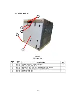
Page 21: ... DESCRIPTION QTY 1 08 5433 Copper Tubing Dia x 6 Length 2 2 10 2793 Elbow 90 IPS Brass 1 3 92 0225 Bushing x NPT Hex Stainless Steel not Shown 1 4 92 0021 Elbow 90 5 8 Compression x MNPT Brass 1 5 92 0008 Panel Rear 4 Pan 1 5 92 0357 Panel Rear 6 Pan 1 3 2 4 5 1 ...

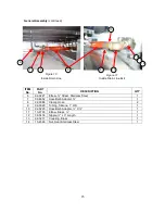
Page 22: ...TION QTY 6 92 0227 Elbow Street Stainless Steel 1 7 08 4852 Hose Barb Adapter 1 8 92 0088 Clamp Hose 2 9 92 0090 Tubing Silicone 1 OD 1 10 92 0220 Hose Barb Adapter X 1 11 10 2793 Elbow Brass 1 12 08 5436 Nipple x 3 Length 1 13 92 0217 Coupling Brass 1 14 10 4586 Nut Seal Stainless Steel 1 6 7 8 9 8 10 11 12 13 14 ...

Page 23: ...ure 12 View looking up from behind Control Panel Figure 13 Left Side Full view Open ITEM No PART No DESCRIPTION QTY 1 92 0069 Terminal Block 1 2 08 6308 Reed Proximity Switch Door Safety Switch 1 See Figure 14 For Details See Figure 15 For Details 1 2 ...

Page 24: ...N QTY 3 92 0183 Controller Temperature 240V 1 4 92 0189 Relay 220V DPDT 2 5 92 0230 Controller Waterfill 208V 240V 1 6 92 0186 Buzzer 240V 2 7 92 0140 Terminal Strip 6 Pole 2 8 92 0414 Fuse 2 Amp 2 9 08 6469 Fuse Block Holder 2 10 92 0228 Timer Delay 1000sec 230V 1 11 92 0187 Timer Delay 1 60 sec 220V 1 6 5 7 8 9 4 3 10 11 ...

Page 25: ...43 Contactor 240V 2 13 92 0140 Terminal Strip 6 Pole 1 14 92 0199 Heater Element Alum for all 208V units 4 4 Pan unit 5 6 Pan unit 14 92 0411 Heater Element Alum for all 240Vunits 4 4 Pan unit 5 6 Pan unit 14 92 0412 Heater Element Alum for all 480V units 4 4 Pan unit 5 6 Pan unit 15 92 0704 Tubular Heater for all 240Vunits 1 15 92 0731 Tubular Heater for all 480V units 1 16 92 0732 Gasket Tubular...

Page 26: ...ntinued Figure 17 Slide Out Control Panel ITEM No PART No DESCRIPTION QTY 17 92 0185 Light Red 250V 1 18 92 0184 Light Amber 250V 1 19 92 0231 Light Green 250V 1 20 92 0125 Rotary Switch 4 Position 1 21 92 0137 Timer 240V 60 Minutes 1 17 18 19 20 21 ...

Page 27: ...M No PART No DESCRIPTION QTY 1 08 6905 Fan Motor 230V 1 2 08 5601 Pulley 25 Dia Bore 22 Teeth 1 3 08 5600 Pulley 25 Dia Bore 18 Teeth 1 4 92 0606 Mounting Pedestal 1 5 92 0605 Mounting Plate 1 6 92 0676 Blower Drive Insulation Not Shown 1 7 08 1414 Belt 1 8 92 0016 Convection Fan Blower Wheel 1 8 1 2 3 4 5 6 7 ...

Reviews: