


4.3 ELECTRICAL CIRCUITS
120 volt a-c power is supplied to the fan motor,
indicator light, and ignition control board, which in turn
controls power to the burner electrodes. IGNITION RESET
switch, and gas valve solenoid Input power is connected at
the junction box mounted (behind an access cover) at the
lower right rear of the oven.
4.3.1 Control Circuit Components
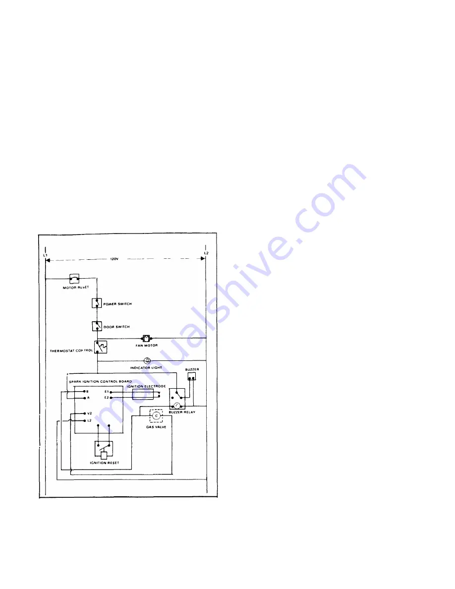
The control circuit is shown in the simplified schematic
drawing Figure 4-2. A brief description of major electrical
control circuit components is included in the following
paragraphs.
4.3.1.1 Door Interlock Switch
The interlock switch is a single pole, two-position
micro-switch with normally open contacts. The switch lever
is operated by an actuating
Figure 4-2 Simplified Schematic — Controls in OFF position
bar built into the door jamb of the right side door When the
door is open, the bar remains retracted with the switch
contacts in the norm ally open position. When the door is
closed, the door pushes the actuating bar against the switch
lever to close the contacts. Connected into the circuit for the
fan and ignition system, the door switch interrupts fan
operation and deactivates the ignition system when the door
is opened
4.3.1.2 Thermostat Control
The thermostat is a bulb and capillary type system,
manually adjustable from 200-475°F
(94-246°C)
.The oven is
put into an automatic heating cycle with the setting of the
thermostat to any of its calibrated temperature settings.
Expansion and contraction of gas with in the cap-
illary/bellows s ystem in response to temperature change
opens and closes the thermostat contacts, energizing and
de-energizing the ignition control system
4.3.1.3 Direct Spark Ignition System
The direct spark ignition system consists of the
electrodes, ignition control board, and as sociated wiring. On
a call for heat, input power is applied to the control board.
Sparking is then initiated and the gas valve is energized.
Sparking continues with the gas valve powered for a "trial
for ignition" period of 3.3 seconds. If flame has not been
established by the end of the trial period, the system will
lock out, the gas valve will close, the reset function will trip
out, and a warning buzzer will sound. Reset action is man-
ually accomplished by pressing IGNITION RESET switch In
normal operation, as soon as flame is established and
proven by the flame sensing circuitry, sparking will cease
immediately and the system will remain "on", monitoring the
flame until the end of the duty cycle. Should flame-out occur
during the duty cycle, the sys tem will reactivate the spark to
provide for reignition.
The flame will either be reestablished or the system will
lock out in the normal manner. Should lock-out occur, the
system is reactivated by the IGNITION RESET switch
located on the control panel.
4-2
Summary of Contents for 2500 HE
Page 7: ...Figure 2 2 28 711mmi Open Stand Inverted for Assembly Figure 2 3 Stacked Ovens ...
Page 13: ...HIGH EFFICIENCY CONVECTION OVEN 3 2 ...
Page 26: ...MAINTENANCE Figure 6 3 Air Shutter Adjustment 6 5 ...
Page 28: ...Figure 7 1 Frame and Cabinet Assembly ...
Page 30: ...HIGH EFFICIENCY CONVECTION OVEN Figure 7 2 Gas Burner and Manifold Assembly 7 4 ...
Page 32: ...7 6 HIGH EFFICIENCY CONVECTION OVEN Figure 7 3 Door Assembly ...
Page 34: ...HIGH EFFICIENCY CONVECTION OVEN 7 8 Figure 7 4 Control Panel Assembly ...
Page 36: ...7 10 HIGH EFFICIENCY CONVECTION OVEN Figure 7 5 Ignition Control Board Assembly ...