

1. Specifications
Connectors:
6100846 - (6) ST, (1) 3.5 mm power input, or
6100845 - (3) duplex SC, (1) 3.5 mm power input
Data Rates:
Transparent to optical signal rates and formats
Switching Speed:
5 msec typical, 10 msec maximum
Sensitivity:
750 to 1450 nanometers
Optical Loss:
less than 3.0 dB typical per FOTP-171 method B1
Compatibility:
62.5/125 µm multimode fiber
Crosstalk:
-45 dB typical per FOTP-42
Temperature:
0 to 40ºC operating, -20 to 70ºC storage
Relative Humidity:
95% max, non-condensing
Mean Time Between Failures:
100,000 hours or 1,000,000 cycles
Power:
100-240 VAC, 50/60 Hz wallmount power supply, 12VDC output
Size:
2.5”H x 8.1”W x 10.8”D
Weight:
2.5 lb.
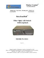
2. Introduction
The Fiber Optic A/B Switch with Loopback is an all optical, fiber optic, latching style A/B switch (maintains the
connection even when power is removed) that includes additional optical switching mechanisms to automatically
loopback the unselected port. For example, if position A is selected, the A port will be connected to the C port, while
any signals received on the B port will be looped back out port B. Likewise, if position B is selected, the B port will
be connected to the C port, while any signals received on the A port will be looped back out port A. This is
especially useful in failover applications, as this added functionality allows the “unused” circuit to be continuously
tested to insure that it is operating correctly and available for use if needed.
3. Installation
Place the switch in a location that is relatively free from vibration and mechanical disturbances.
Apply power to the switch by plugging the AC power supply module into the connector on the back of the switch,
and then plug the power supply module into a suitable source of AC power. Next, change the connection states of
the switch by rotating the front panel control knob between the A and B positions. This causes all of the internal
optical switch mechanisms to switch to an appropriate connection state prior to making any fiber optic cable
connections to the switch. As soon as the fiber optic cables are attached, the network connection between the C
port and the selected network port (A or B) will be immediately active.
Now that the switch connection state is configured for your application, connect the “shared” network connection to
the Port C fiber optic connectors. Connect the one fiber link (of the two to be switched) to Port A. Connect the
second fiber link to Port B
Take care to connect inputs and outputs consistently.