Mark 06 62 611 Technical Manual Download Page 4

4

                                                                                                     HMI-EC (06 99 150) 

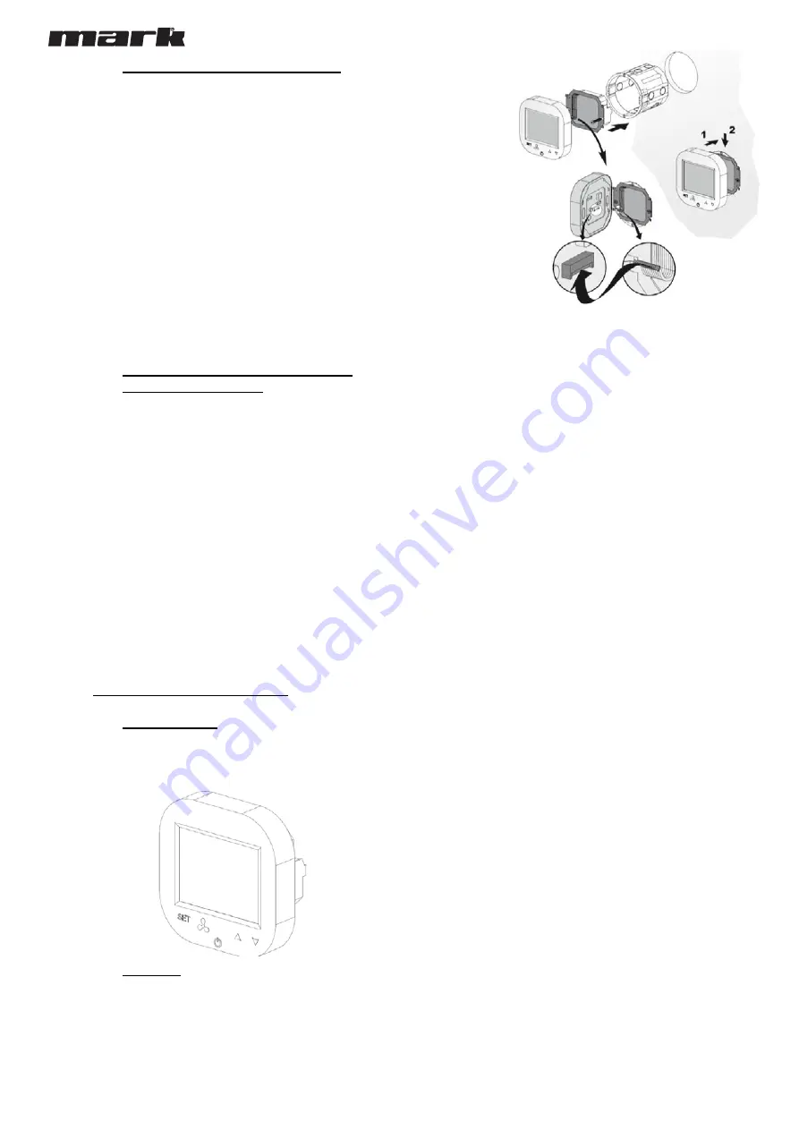
4.4.  CONTROLLER FLUSH MOUNTING 

Apply the following sequence of actions while flush mounting of this controller: 

 Install the flush mounted junction box (

1

 Cross all cables through the junction box and prepare their ends for plugging into 

controller’s termina

l block (remove the shields and apply end sleeves if justified) 


Plug the wires into the controller’s terminal block according to relevant wiring diagram 

(above listed). Ensure that cables are properly plugged and are not loose. 

 Install the rear power part of the controller in the flush mounted junction box and tight 

both sides screws (

2

 Plug the strip cable to the terminal in the front part of controller (

3

 Mount the front part of the controller on the rear one (

4


CAUTION

. After all installation works, check if the flush mounting is properly done (the 

controller is fixed in the wall and is not loose).

4.5.  OTHER INSTALLATION FACTS AND 

RECOMMENDATIONS 

  Type of flush mounting junction box: 

o

  Flush mounted junction box Ø 60 mm, minimum depth 

of the box: 10 cm 

  Flush mounted part of the controller: 

o

  Rear power supply unit 

  Minimum height of the installation 

o

  1,5 m above floor level 

  Minimum clearance between the controller (side edges of 

the front display part) and the surrounding  parts of the 

fitment: 

o

  10 cm 

  The minimum dimensions of ventilating openings and their 

correct arrangements 

o

  N/A 

  Power supply wires 

o

  2 x 1 mm

2


o

  Temperature of the wire insulation: 176 °F (80 °C) 

  Door temperature sensor and communication wires 

o

  2 x 0,5 mm

2

 LIYCY and 2 x 0,5 mm

2

 LIYCY 

  Temperature of the wire insulation: 176 °F (80 °C) 


5.  OPERATIONS ON THE HMI-EC 

5.1.  FRONT PANEL 

The front panel of the HMI-EC consists of the large display and 

set of buttons enabling full handling of the controller and the 

EASYAIR unit 


Function of each button of the HMI-EC  controller are as per 

following description: 

 LCD Screen 

  displays all information related with 

EASYAIR  unit operations like status, calendar settings, 

alarm information etc. 

 SET 

 approval of selected function of parameter 

 Fan button 

 for easy toggling between available speeds of 

the fan revolutions 

 On-Off button 

  main switch of the entire EASYAIR 

curtains 

 Arrow up 

  toggles between the menu items in upwards 

direction 

 Arrow down 

  toggles between the menu items in 

downwards direction 

5.2.  DISPLAY 

The display of the HMI-EC  Controller consists of the following 

elements 

Note: Some of the display elements are not in use for EASYAIR 

Air Curtains. Table below show only elements specific for HMI-EC 

system.  

Summary of Contents for 06 62 611

Page 1: ...HMI EC CONTROL PANEL06 62 611 NL Technical manual Technisch boek EN HMI EC HMI EC CONTROL PANEL 06 99 Installation and operating...

Page 2: ...6 99 150 EASYAIR W100 EC EASYAIR E100 EC EASYAIR W150 EC EASYAIR E150 EC EASYAIR W200 EC EASYAIR E200 EC The part of oach model name is a power supply standard desctiption volts phases hertz 3 TERMINA...

Page 3: ...LER TO EASYAIR E100 150 200 MODEL to 400 3 50 Connect the HMI EC to the EASYAIR E100 150 200 air curtains according to diagram shown on Figure 3 Figure 3 EASYAIR E100 150 200 connections 4 3 CONNECTIO...

Page 4: ...imum clearance between the controller side edges of the front display part and the surrounding parts of the fitment o 10 cm The minimum dimensions of ventilating openings and their correct arrangement...

Page 5: ...rd lock indicator Fan status indicator Schedule chart 5 3 SWITCHING THE CONTROLLER ON AND OFF Before attempting to any basic operations with this controller you need to switch it on To switch the cont...

Page 6: ...set present time and day of the week 5 5 2 SCHEDULE SETTING Having the controller in active mode press the Set button and hold it for 5 seconds The controller will enter the time weekly schedule sett...

Page 7: ...atically For advanced settings A group the following parameters can be modified No Function Set point B0 Temperature units C F B1 Min Temperature 41 104 o F 5 15 C B2 Max Temperature 61 104 o F 16 40...

Page 8: ...chtgordijnen HMI EC 06 99 150 EASYAIR W100 EC EASYAIR E100 EC EASYAIR W150 EC EASYAIR E150 EC EASYAIR W200 EC EASYAIR E200 EC Het deel van elke modelnaam is een standaardbeschrijving van de voeding vo...

Page 9: ...OP EASYAIR E100 150 200 MODEL 400V 3 50HZ Sluit de HMI EC aan op de EASYAIR E100 150 200 luchtgordijnen volgens het schema in Figuur 3 Figure 2 EASYAIR E100 150 200 aansluiting 4 3 AANSLUITING VAN HM...

Page 10: ...te deel van het display en de omliggende delen van het hulpstuk o 10 cm De minimale afmetingen van ventilatieopeningen en hun juiste rangschikking o N v t Voedingskabels o 2 x 1 mm2 o Temperatuur van...

Page 11: ...Indicator status ventilator Schema grafiek 5 3 DE CONTROLLER IN EN UITSCHAKELEN Voordat u begint met het uitvoeren van basisbewerkingen met deze controller moet u deze inschakelen Om de controller in...

Page 12: ...ijl omlaag knop ingedrukt De controller gaat naar de instellingenmodus voor tijd dag zodat u de huidige tijd en dag van de week kunt instellen 5 5 2 SCHEMA INSTELLING Met de controller in actieve modu...

Page 13: ...eerde parameters met de knoppen en v Nadat de wijzigingen zijn aangebracht verlaat u de instellingenmodus door op de aan uit knop van de controller te drukken Uw instellingen worden automatisch opgesl...

Page 14: ...belgium be MARK DEUTSCHLAND GmbH MAX PLANCK STRASSE 16 46446 EMMERICH AM RHEIN DEUTSCHLAND TELEFON 49 0 2822 97728 0 TELEFAX 49 0 2822 97728 10 info mark de www mark de MARK POLSKA Sp z o o UL JASNOG...

Reviews: