


Series TSTM-DC Test Stands
User’s Guide
5
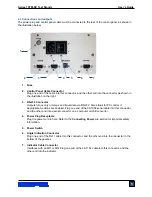
2.3 Connections and outputs
The power plug and control panel cable must be connected to the rear of the control panel, as shown in
the illustration below:
1. Fuse
2. Control Panel Cable Connector
Plug one end of the cable into this connector, and the other end into the connector as shown in
the illustration on the right.
3. RS-232 Connector
Outputs torque only or torque and travel data via RS-232. Also allows for PC control, if
appropriate functions are enabled. Plug one end of the 09-1056 serial cable into this connector,
and the other end into a serial connector on a computer or USB converter.
4. Power Plug Receptacle
Plug the power cord in here. Refer to the
Connecting Power
sub-section for important safety
information.
5. Power Switch
6. Angle Indication Connector
Plug one end of the RJ11 cable into this connector, and the other end into the connector in the
bottom of the gearbox.
7. Indicator Cable Connector
Interfaces with an M7I or M5I. Plug one end of the 09-1162 cable into this connector, and the
other end into the indicator.
1
2
3
4
6
7
5
Summary of Contents for TSTM-DC
Page 1: ...Series TSTM DC Motorized Torque Test Stands User s Guide...
Page 23: ...Series TSTM DC Test Stands User s Guide 23 10 DIMENSIONS in mm TSTM DC...
Page 24: ...Series TSTM DC Test Stands User s Guide 24 TSTMH DC CONTROL PANEL...
Page 25: ...Series TSTM DC Test Stands User s Guide 25 NOTES...


