SeaMach 24 VDC
Rooftop Air Conditioners
SeaMach 24 VDC Rooftop Air Conditioner Installation Manual 5/2013
Page 13 of 20
FIGURE 7
Page 1: ...oof 8 Chapter 7 Electrical Wiring 9 Chapter 8 Installing the Ceiling Assembly 9000 Series 11 Chapter 9 Completing the Installation 9000 Series 14 Chapter 10 Installation Programming and Operation of the o Touch Thermostat 14 Chapter 11 Maintenance 20 Manufactured by P N 01991 5 2013 New Marvair Division of AIRXCEL Inc PO Box 400 Cordele GA 31010 156 Seedling Dr Cordele GA 31015 229 273 3636 Fax 22...
Page 2: ... see this symbol on the Marvair unit and in the instruction manuals be alert to the potential for personal injury Understand the signal word DANGER WARNING and CAUTION These words are used to identify levels of the seriousness of the hazard DANGER Failure to comply will result in death or severe personal injury and or property damage WARNING Failure to comply could result in death or severe person...
Page 3: ...d Chapter 3 Air Conditioning Sizing The ability of an air conditioner to provide a comfortable environment for the consumer is dependent upon the following conditions Air conditioners are rated primarily by their ability to remove heat The thermal measurement used for detecting a gain or loss of heat is the British Thermal Unit BTU One 1 BTU is the amount of heat required to raise the temperature ...
Page 4: ...ator closets cabinets Chapter 5 Installing The Roof Top Unit DANGER SHOCK HAZARD DISCONNECT ALL POWER BEFORE PERFORMING ANY CUTTING CONTACT WITH HIGH VOLTAGE CAN RESULT IN EQUIPMENT DAMAGE PERSONAL INJURY OR DEATH CAUTION TO PREVENT DAMAGE TO THE WIRING AND BATTERY DISCONNECT THE BATTERY CABLE FROM THE POSITIVE BATTERY TERMINAL BEFORE PERFORMING ANY CUTTING TO THE VEHICLE OR VESSEL Once the locati...
Page 5: ...ing the roof outer surface and interior ceiling apart so that when the 2 roof top air conditioner and ceiling assembly are bolted together no collapsing occurs Airxcel s SeaMach air conditioner requires that the spacing from the vehicle roof top to the interior ceiling be no less than 1 2 34 cm A typical support frame is shown in Figure 1 The frame must provide an opening to allow passage for the ...
Page 6: ...lation Manual 5 2013 Page 6 of 20 FIGURE 3 15 DEGREE MAX ABOVE LEVEL 15 DEGREE MAX ABOVE OR BELOW LEVEL NOTE IF UNIT IS INSTALLED UNLEVEL FRONT TO BACK THE NOSE OR FRONT OF THE UNIT MUST BE UP DO NOT INSTALL NOSE DOWN ALLOWABLE OFFSET FOR ALL HEAT PUMPS WITH ROTARY COMPRESSORS FIGURE 2 ...
Page 7: ...oof top air conditioner level A typical leveling shim is shown in Figure 3 After the mounting hole area is properly prepared remove the carton and shipping pads from the roof top air conditioner Carefully lift the unit to the top of the vehicle Do not use the outer plastic shroud for lifting Place the roof top air conditioner over the prepared mounting hole The pointed end nose of the shroud must ...
Page 8: ...itioner to the roof Refer to Figure 4 Locate the air conditioner mount gasket over the 14 35 6 cm to 15 38 cm square opening in the A roof Install the ceiling assembly mount frame using the four bolts found with the ceiling assembly B Proper tension has been achieved for each bolt when any portion of each gasket indicating tab has been C pulled down even with the roof See Figure 4 The upper unit h...
Page 9: ...in Wire Watts at 24V 14 12 10 8 6 4 2 1 0 2 0 3 0 1 24 169 262 412 675 2 48 84 131 207 337 532 4 96 37 66 103 169 267 6 144 28 45 66 112 178 282 8 192 21 32 54 84 133 216 10 240 17 26 43 67 107 169 270 15 360 11 17 26 45 71 112 180 289 20 480 13 21 37 54 84 135 217 270 343 25 600 17 26 43 67 108 172 217 274 30 720 13 22 36 56 90 144 180 228 40 960 17 26 43 67 108 135 171 50 1200 13 21 34 54 86 108...
Page 10: ...SeaMach 24 VDC Rooftop Air Conditioners SeaMach 24 VDC Rooftop Air Conditioner Installation Manual 5 2013 Page 10 of 20 ...
Page 11: ...TO A GROUNDING LUG EITHER IN THE SERVICE BOX OR THE MOTOR GENERATOR COMPARTMENT Chapter 8 Installing The Ceiling Assembly 9000 Series Make sure that you have properly matched the roof top air conditioner and interior ceiling assembly The following step by step instructions must be performed in the following sequence to insure proper installation A Carefully uncarton the ceiling assembly Controls a...
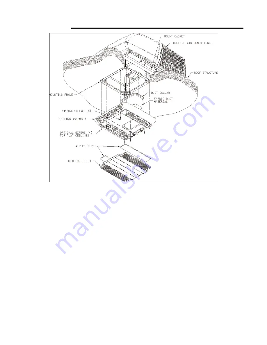
Page 12: ...e to the mounting frame with 4 provided shoulder screw spring H assemblies The front two screws should pass through the clearance holes in the metal control box shield See Figure 7 The ceiling assembly shroud is curved to contour to a crowned ceiling If installation is to a flat I ceiling and gaps are present on the sides of the shroud insert the four optional 3 4 inch 19 mm screws provided throug...
Page 13: ...SeaMach 24 VDC Rooftop Air Conditioners SeaMach 24 VDC Rooftop Air Conditioner Installation Manual 5 2013 Page 13 of 20 FIGURE 7 ...
Page 14: ...eration and maintenance instructions Customer Envelope Package Chapter 10 Installation Programming and Operation of the o Touch Thermostat Introduction When connected to a 12 24VDC controller the versatile o Touch DC digital display provides room temperature control and humidity reduction in a small package It allows for easy control of fan speed operating mode and temperature in a wide variety of...
Page 15: ...ll show in the center of the screen along with the fan and on off symbol The fan may be operated in this mode by pressing the fan symbol Press the On Off button to access other operating modes Operating Display Temperature Set Point Mode Symbol Ambient Temperature On Off Symbol Fan Speed Indicator Fan Operating I O Operating Modes Two operating modes are available and can be changed by pressing th...
Page 16: ...ation as shown above Press and hold the lower center of the display where the fan speed indicator is located to view this status To exit the status view press anywhere on the display The system current is available at all times the remaining items only during compressor operation Failure Messages The following fault messages will be shown on the display in the event of a failure AIR SENSOR TROUBLE...
Page 17: ... Cycled Pump When set for Cycled the pump will run on demand When set for Continuous the pump will run continuously when the system is in cool mode Fan Speed 1 6 These parameters are used to optimize fan performance and airflow Speed 1 corresponds to the lowest speed setting Speed 6 corresponds to the highest speed setting Speeds should be set to avoid system icing in humid environments Maximum Co...
Page 18: ... 29 4 C Ambient temperature range displayed 5 F to 150 F 15 C to 65 6 C Sensor accuracy 2 F at 77 F 1 1 C at 25 C Evaporator Output MAX 10 Amps Condenser Output MAX 10 Amps System Current MAX 60 Amps Minimum operating temperature 0 F 17 8 C Maximum operating temperature 180 F 82 2 C Maximum RH conditions 95 Non condensing Maximum length of the display cable 75 Feet 22 86 m ...
Page 19: ...SeaMach 24 VDC Rooftop Air Conditioners SeaMach 24 VDC Rooftop Air Conditioner Installation Manual 5 2013 Page 19 of 20 ...
Page 20: ...ly by qualified service personnel Contact your nearest Service Center if electrical problems should arise Check Points B Failure to start or to cool the air are sometimes problems with air conditioning units The air conditioner is designed to operate on 24 VDC electrical power If the compressor on the air conditioner fails to start check with your Service Center to determine that the proper wire s...