


marinco.com | 800.307.6702
2
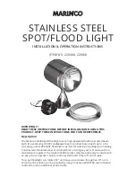
INSTALLATION INSTRUCTIONS:
STAINLESS STEEL FLOOD/SPOT LIGHT
Tools for Installation
Tools and additional materials required:
• Electric drill with 2-3/4" hole saw bit
• 5/8", 1/8" and 3/32" drill bits
• Phillips-head screwdriver
• (3) #10 x 3/4" SS phillips pan-head self-
tapping screws (or #10 machine screws,
lock washers and nuts.)
• Non-silicon sealant (StarBrite
®
Boat
Caulk #83801 or equivalent)
• (2) # 8 x 3/4" SS pan head self-tapping
screws
• ½" cable clamps with screws (to fasten
control cable to interior surfaces)
Mounting the Spotlight
1) Select a flat, smooth surface on which to mount the spotlight. Be sure that you will
have access to the underside of the chosen location, and that you can drill holes
there without damaging existing wiring or structures. Avoid locations where lines,
anchor, sails or other hazards might damage the light.
Note: Mounting the light as far forward as possible can help to reduce reflected glare
when the light is in use.
2) Mark the locations of the three base mounting holes and center the wire harness
hole onto the mounting surface with a pencil.
3) Drill 1/8" pilot holes into the mounting surface at the marked points.
4) Place the mounting gasket on the base of the spotlight, making sure that the
harness exits through the center hole of the gasket.
5) Feed the wires from the base of the spotlight through the center hole in the
mounting surface. A small amount of non silicone sealant can be applied to the
pilot holes and around the wire harness where it penetrates the mounting surface.
6) Place the light on the mounting surface, and fasten the spotlight securely using
three #10 self tapping Phillips pan-head screws. Do not over tighten the fasteners.
Mounting the Control Panel
1) Select a convenient mounting location for the control panel. Be sure you will have
access to the area behind the location, and can drill holes there without damaging
existing wiring or structures. Do not place the control where it could interfere with
the safe operation of the vessel or vehicle. Avoid mounting the control panel on a
surface exposed to the elements or spray.
2) Drill two 1/16" pilot holes for the hole saw at the locations shown on this template.
Be sure they are level and spaced 13/16" apart.
CAUTION: Always wear eye protection when using power tools!
3) Next, use the hole saw to cut a 2-3/4" hole.
4) Feed all the wires through the center hole. Test fit the control panel into the hole.
Use a file to enlarge the hole if necessary.
5) Use a pencil to mark the locations of the two small holes in the panel onto the
mounting surface. Remove the control panel, then drill a 3/32" pilot hole at each of
the marked locations.