


J2K100 User’s Manual
3 J1939 Network Basics
Like an NMEA 2000
®
network, a J1939 network is based on Controller Area Network (CAN)
technology. A CAN network consists of two or more nodes, and for J1939 networks, they
usually include one or more engines and the corresponding engine displays. In addition to the
nodes or electronic boxes, a CAN network consists of the cabling system, which is used to
interconnect the nodes. At both ends of the network are terminating resistors (121
Ω
) that are
used to terminate the line in its characteristic impedance to prevent reflections or ringing on the
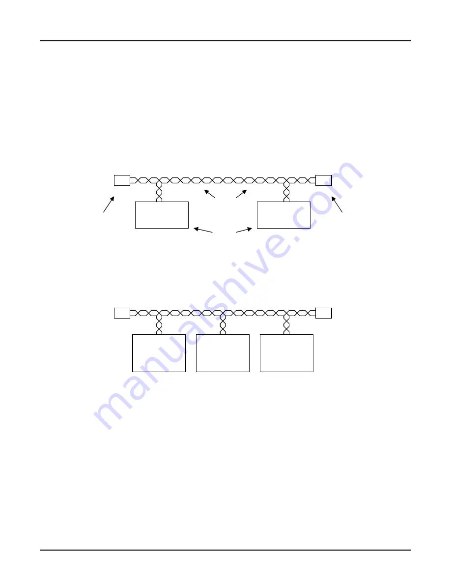
network. J1939 is typically wired using twisted pair for the two data lines. Figure 2 shows a
typical J1939 network with a single engine and a single display.
J1939
Engine
J1939
Display
Termination
Resistor
Termination
Resistor
Cabling System
(Most Likely
Twisted Pair )
Nodes
Figure 2 - Typical Single Engine J1939 Network
Another example showing a two engine, single J1939 network is given below in Figure 3.
Port
J1939
Engine
J1939
Display
Starboard
J1939
Engine
Figure 3 – Two Engine, Single J1939 Network
The two engine, single J1939 network shown in Figure 3 requires the individual engines to use
different source addresses so that the display can distinguish which data packets or messages
are associated with which engine (J1939 and NMEA 2000
®
refer to the messages as
Parameter Group Numbers or PGNs). Usually, but not always, the port engine is assigned to
address 0 while the starboard engine is assigned to address 1 by the engine manufacturer.
Another example showing two engines with, dual J1939 networks is given below in Figure 4.
Page B4
Appendix B – Application Note
Revision 1.1