background image


58 

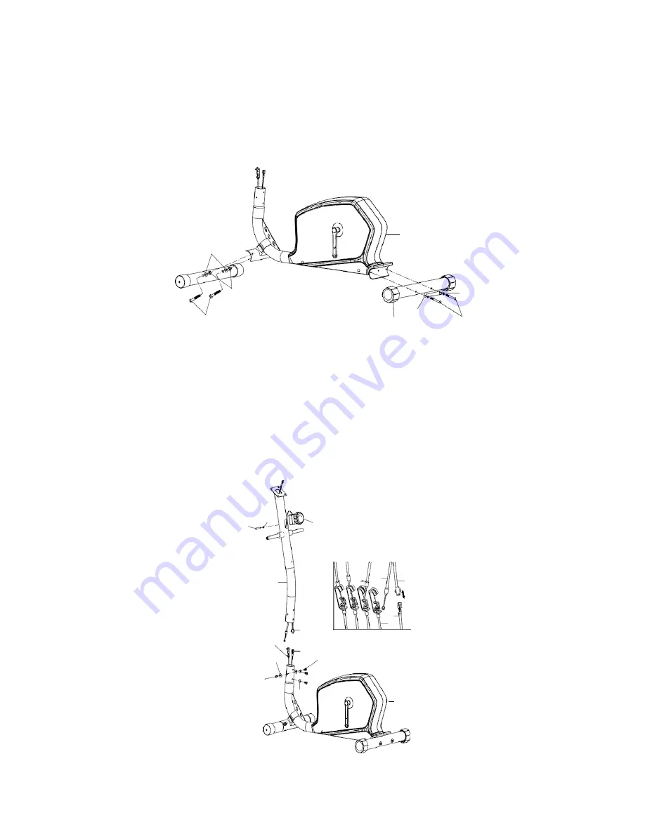
ASSEMBLY INSTRUCTION 


STEP 1 

Attach rear stabilizer (3) to main frame (1), tighten with two sets of curve washer (5) and 
allen bolt (2). Then attach the front stabilizer (6) to the main frame (1) , tighten with two sets 
of carriage bolt (23) ,curve washer (24) and domed nut (36). 


  1 

24 


36 

23 

STEP 2 

2


Insert the cable of the tension control (55) into the opening of the front post 
(9).  Secure using one flat washer (56) and one screw (57) which are 
pre-assembled on the tension control. 
Connect the extension lower sensor wire (50) with the middle sensor wire (51). 
Turn the tension control knob w/cable (55) to level 8, connect it to extension tension 
cable (58). 
Insert the front post (9) into the main frame (1) and secure using four allen bolts (47) 
and four curve washers (5). 


57 

56 

55 


55 

51 


50 

51 

58 

50 47 

47 

Summary of Contents for 1201E

Page 1: ...1201E ELLIPTICAL CROSS TRAINER USER MANUAL Distributed By Pure Tec Limited www puretecfitness com ...

Page 2: ...eight Limit Capacities Hardware Parts List 4 5 Pre Assembly Check List 6 Assembly Instructions 7 11 Computer Instructions 12 13 Exercise Instructions 14 15 Exploded Diagram 16 17 Parts List 18 19 Additional Information 20 Warranty Information 21 ...

Page 3: ...h is clear of all obstacles as not to restrict movement whilst exercising DO NOT use the Trainer near water or outdoors 7 Exercise equipment has moving parts In the interest of safety keep others especially children at a safe distance while exercising 8 Never hold your breath while exercising Breathing should remain at a normal rate in conjunction with the level of exercise beingperformed 9 Rest a...

Page 4: ... 2 5 Curve washerФ8 Ф20 1 5 8 21 Hollow carriage nutФ8 20 4 22 Allen bolt M6 12 4 23 Carriage bolt M10 75 2 24 Curve washer 10 Ф22 1 5 2 25 End cap 6 26 Flat washerФ10 Ф32 2 27 Spring washerФ10 2 28 Hex head bolt M10 20 2 29 D type washer 2 31 Hex head bolt M8 45 4 32 Hex head bolt M10 78 2 ...

Page 5: ...10 2 36 Domed nut M10 2 37 Flat washerФ10 Ф22 1 5 2 40 Hinge bolt L R 1 1 42 Club knob 4 43 Wave washer 2 44 Nut R L 1 1 45 Flat washerФ27 Ф13 2 5 2 47 Allen bolt M8 16 6 Allen wrench 2 Allen Key L6 1 Allen Key L4 1 Allen Key L8 1 ...

Page 6: ...49 NO DESCRIPTION Q TY 1 Main Frame 1 9 55 Front post Tension control knob w cable 1 1 52 53 Bottom handlebar L R 1 1 12 13 Top handlebar L R 1 1 41L R Pedal tube L R 1 1 11 Fixed handlebar 1 6 Front stabilizer 1 3 Rear stabilizer 1 10 Computer 1 48 49 Pedal L R 1 1 ...

Page 7: ...nsert the cable of the tension control 55 into the opening of the front post 9 Secure using one flat washer 56 and one screw 57 which are pre assembled on the tension control Connect the extension lower sensor wire 50 with the middle sensor wire 51 Turn the tension control knob w cable 55 to level 8 connect it to extension tension cable 58 Insert the front post 9 into the main frame 1 and secure u...

Page 8: ...ng on the wire holder on sensor wire Connector Pull the extension sensor wire Connector backward and slide the wire through the slot on the bracket Drop down the Connector so the fitting sits firmly on top of the bracket NOTE In able to hold the Front Post while connecting the cables and wires extra help may be needed ...

Page 9: ...middle sensor wire 51 with computer 10 then attach computer 10 to bracket on front post 9 tighten with four screws 20 11 10 51 20 60 47 5 46 9 1 STEP 4 Attach bottom handlebar L 52 to front post 9 Secure using one D type washer 29 flat washer 26 spring washer 27 hex head screw 28 Repeat for bottom handlebar R 53 Attach two end cap 25 to the hex head screw 28 27 25 29 29 28 25 27 26 28 26 53 52 9 1...

Page 10: ... then fasten and secure with one washer 37 and nylon nut 34 Then attach two end caps 25 to hex head bolt 32 Repeat above procedure for pedal tube R 41R and bottom handlebar R 53 53 34 33 32 25 52 37 25 43 40R Step6 25 33 32 34 25 37 41L 40L 43 44L 45 44R 1 41R 45 Insert the top handlebar L 12 into the bottom handlebar L 52 tighten with two hollow carriage nuts 21 and allen bolts 22 Repeat for top ...

Page 11: ...11 Step7 Attach pedal L 48 to pedal tube L 41L tighten with two hex head bolt 31 and club knob 42 Repeat for pedal R 49 31 49 42 31 1 48 42 CHECK ALL BOLTS AND NUTS ARETIGHTENED BEFORE USING THE MACHINE ...

Page 12: ...art toend 2 Press MODE button unit CAL appears Press SET button to set exercise calories When the set is zero the computer will alarm 15 seconds 6 PULSE Press MODE button until PULSE appears Before measuring your pulse rate please place your palms of your hands on Both of your contact pads and the monitor will show your current heart beat rate in beats per minute BPM on the LCD after 6 7 seconds R...

Page 13: ...ME 00 00 99 59 CURRENT SPEED The maximum signal can be pickup is 99 9KM H TRIP DISTANCE 0 00 99 99KM or 0 00 9999KM CALORIES 0 1 999 9kCAL PULSE RATE 40 206BPM BATTERY TYPE 2pcs of SIZE AA or UM 3 OPERATING TEMPERATURE 0 C 40 C STORAGE TEMPERATURE 10 C 60 C ...

Page 14: ...t is advisable to do a few stretching exercises as shown below Each stretch should be held for approximately 30 seconds do not force or jerk your muscles into a stretch if it hurts STOP SIDE BENDS OUTER THIGH 2 The Exercise Phase This is the stage where you put the effort in After regular use the muscles in your legs will become more flexible Work to your but it is very important to maintain a ste...

Page 15: ...ROSS TRAINER you will need to have the resistance set quite high This will put more strain on our leg muscles and may mean you cannot train for as long as you would like If you are also trying to improve your fitness you need to alter your training program You should train as normal during the warm up and cool down phases but towards the end of the exercise phase you should increase resistance mak...

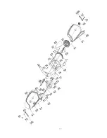
Page 16: ... 13 10 22 21 12 5 22 21 46 60 20 56 55 57 29 27 25 30 28 29 25 27 30 54 9 54 30 26 30 28 26 52 5 5 47 53 35 35 47 31 49 33 25 43 35 35 7 51 58 50 36 24 7 34 32 37 25 41R 42 39 1 45 44R 40R 34 25 25 33 37 23 6 31 48 44L 4 8 5 8 3 2 32 39 41L 42 45 40L 43 47 ...

Page 17: ...17 ...
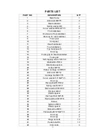
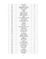
Page 18: ...6 Foam grip 2 17 Self tapping screw ST4 20 2 18 WasherФ4 2 Ф12 2 19 Hand pulse sensor 2 20 Screw M5 10 4 21 Hollow carriage nutФ8 20 4 22 Allen bolt M6 12 4 23 Carriage bolt M10 75 2 24 Curve washer 10 Ф22 1 5 2 25 End cap 6 26 Flat washerФ10 Ф32 2 27 Spring washerФ10 2 28 Hex head bolt M10 20 2 29 D type washer 2 30 Plastic spacer 4 31 Hex head bolt M8 45 4 32 Hex head bolt M10 78 2 33 Sleeve 2 3...

Page 19: ... 59 Crank L R 1 1 60 Grommet 1 61 Screw ST5 15 4 62 Flywheel 1 63 Self tapping screw ST5 15 8 64 Crank cover 2 65 Chain cover left 1 66 Chain cover right 1 67 Belt drive wheel 1 68 Belt 1 69 BB assembly 1 70 Sensor bracket 1 71 Magnetic assembly 1 72 Hex head bolt M8 105 1 73 Spacer 2 74 WasherΦ8 Φ17 1 75 Nylon nut M8 1 76 Spring 1 77 Hex head nut M6 2 78 Hex head bolt M6 25 1 79 France nut 4 80 B...

Page 20: ...ill come to the end of its useful life Under European WEEE Legislation you are responsible for the appropriate disposal of your Trainer to a recognised public collection facility CARE AND MAINTENANCE 1 Inspect and tighten all parts before using the Trainer 2 The Trainer can be cleaned using a damp cloth and mild non abrasive detergent DO NOT use solvents 3 Examine the Trainer regularly for signs o...

Page 21: ... liable for indirect special or consequential damages arising out of or in connection with the use or performance of the product or other damages with respect to any economic loss loss of property loss of revenues or profits loss of enjoyments or use costs of removal installation or other consequential damages or whatsoever natures The warranty extended hereunder is in lieu of any and all other wa...

Reviews: