Marantz SR6300, User Manual
The Marantz SR6300 Receiver is a high-quality audio product designed to enhance your home theater experience. With its advanced features and superior sound quality, this receiver provides an immersive audio experience. You can easily set up and configure this device using the user manual, which you can download for free from our website.
Share
Download


Reviews:
No comments
Related manuals for SR6300

UFT 171si
Brand: Kathrein Pages: 40

NCA-683
Brand: Naxa Pages: 8

iVIC-6DR
Brand: Vais Technology Pages: 8

RX-V367
Brand: Yamaha Pages: 57

R-V702 R-V502
Brand: Yamaha Pages: 40

RX-V381
Brand: Yamaha Pages: 2

TR-3003
Brand: texet Pages: 28
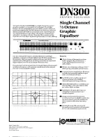
DN300
Brand: Klark Teknik Pages: 2

HTPS-400
Brand: JBL Pages: 8

GI.BI.DI. DOMINO DRC4334
Brand: Bandini Industrie Pages: 2

RF 65
Brand: HopeRF Pages: 72

JWM40
Brand: Jensen Pages: 2

775DI
Brand: Boss Audio Systems Pages: 13

DLR 60 2.0
Brand: Williams Sound Pages: 8

LINK WI-R
Brand: TECshow Pages: 18

T775 HD
Brand: NAD Pages: 46

748UAI
Brand: Boss Audio Systems Pages: 11

BOX M GSM B
Brand: Sminn Pages: 2


