


11
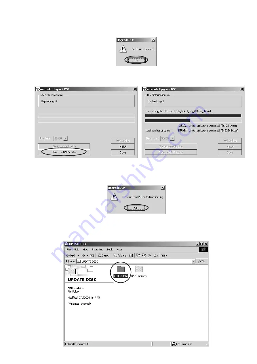
9. If the connection is made successfully, a dialog box saying "Success to connect" appears and "CONNECTED" is
displayed on FLD.
10. Click
Send the DSP codes
button on the dialog box. Progress status of updating will be shown on PC and LOADING is
displayed on FLD.
11. If updating is completed successfully, "COMPLETED"is displayed on FLD. And a dialog box saying "Finished the DSP
code transmitting" appears. Click
OK
and then Application is closed automatically.
12. Turn off the unit.
Download Firmware for CPU (Mode 2)
1. Put the "CPU update" folder into anywhere on your PC’s hard disc.
Summary of Contents for SR5600
Page 18: ...18 17 8 BLOCK DIAGRAM...
Page 19: ...19 20 9 SCHEMATIC DIAGRAM INPUT PWB...
Page 20: ...22 21 DSP PWB 1 2...
Page 21: ...23 24 SR5600 SR5600 DSP PWB 2 2...
Page 23: ...27 28 VIDEO PWB...
Page 24: ...30 29 COMPONENT PWB...
Page 25: ...31 32 VIDEO CONVERTER PWB...
Page 26: ...34 33 AMP PWB...
Page 27: ...35 36 POWER PWB...
Page 31: ...43 44 DSP PWB B IC20 IC35 Lead free Solder When soldering use the Lead free Solder Sn Ag Cu...
Page 35: ...51 11 IC DATA IC21 TC9162 3 4...
Page 36: ...52 IC21 TC9162 3 4...
Page 37: ...53 IC22 TC9273 IC24 TC9499...
Page 38: ...54 IC12 TC90A49F...
Page 39: ...55 IC14 TA1270BF...
Page 41: ...57 IC16 CS4382...
Page 42: ...58 IC16 CS4382...
Page 46: ...62 IC78 LC74781...


