71
2. How to update by DPMS
You can update the firmware by downloading the latest version from the Internet.
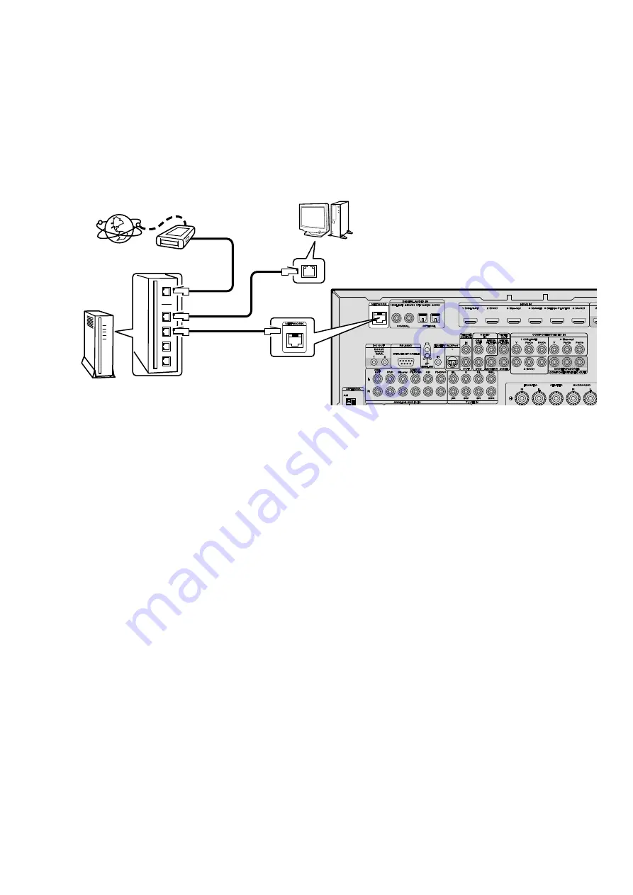
2.1. Connecting to the Network
(1) System requirements
• Internet Connection by Broadband Circuit
• Modem
• Router
• Ethernet cable (CAT-5 or greater recommended)
(2) Setting
2.2. Checking and updating the firmware
Check if the latest firmware exists. You can also check approximately time required to complete an update.
(1) Press the "SETUP" button on the remote control to display the GUI menu.
(2) Use the cursor buttons to select "GENERAL" → "FIRMWARE" → "Update" → "Check For Update".
(3) Press the "ENTER" button.
• The latest version of the firmware on the website is displayed.
• If the firmware on the website is latest, proceed to (4).
• If the latest firmware has been already installed, press the "SETUP" button to close the menu.
(4) Use the cursor buttons to select "START", then press the "ENTER" button.
• During update, the power indicator lights in red and the GUI screen disappears. And an approximately remaining
time is indicated on the display.
• When updating is complete the power indicator lights in green and normal status is resumed.
(5) Press the "SETUP" button to close the menu.
--- Cautions on Firmware Update ---
• In order to update the firmware, you must have the correct system requirements and settings for a broadband Internet
connection.
• Do not turn off the power until updating is completed.
Even with a broadband connection to the Internet, approximately 1 hour is required for the updating procedure to be
completed.
Once updating starts, normal operations on the AV7701 cannot be performed until updating is completed. Also, setting
items of the GUI menu of AV7701 or setting items of the image adjustment may be initialized.
Note down the settings before updating, and set them again after updating.
Modem
Internet
Computer
LAN port/
Ethernet
connector
NETWORK
connector
Router
To WAN port
To LAN port
To LAN port
Summary of Contents for AV7701
Page 15: ...15 7 Remove the screws Shooting of photograph A GEAR DAMPER...
Page 30: ...30 Personal notes...
Page 35: ...Personal notes Personal notes 35...
Page 112: ...112 Personal notes...
Page 115: ...115 LEVEL DIAGRAM RCA PREOUT LEVEL DIAGRAM FRONT ch...
Page 116: ...116 LEVEL DIAGRAM CENTER ch RCA PREOUT...
Page 117: ...117 LEVEL DIAGRAM SUBWOOFER ch...
Page 118: ...118 LEVEL DIAGRAM SURROUND ch RCA PREOUT...
Page 119: ...119 LEVEL DIAGRAM SURR BACK ch RCA PREOUT...
Page 170: ...Personal notes Personal notes 170...
Page 174: ...174 PACKING VIEW 2 8 7 9 1 9 10 11 12 12 z 6 5 6 3 6 1 6 2 6 4 6 7 6 6 6 9 6 8...
Page 181: ...181 R5F3650KNFB HDMI IC231...
Page 193: ...193 MX29LV160DBTI 70G HDMI IC410 MX29LV160DBTI 70G Block Diagram...
Page 195: ...195 AK5358BET HDMI IC451 AK5358BET Pin Function...
Page 208: ...208 NJW1194A AUDIO IC484 IC489 BLOCK DIAGRAM...
Page 209: ...209 2 FL DISPLAY FLD 17 BT 40GINK FRONT FL601 PIN CONNECTION GRID ASSIGNMENT Y2 q...
Page 210: ...210 ANODE CONNECTION...
Page 266: ...266 Personal notes...


