background image

This is due to the fact that extend the same amplitude to the all sub harmonics 
generated, would bring to a “booming” and “dark” result, there where having a 
Peak  on  the  65Hz,  will  leave  the  max  intensity  of  the  synthesized  sub 
harmonics,  in  correspondence  of  the  original  fundamentals,  ranging  around 
130Hz, where typically fall the octave used by the harmonizing instruments as 
the  Bass  or  Kick  Drum,  creating  there  a  bigger  presence  and  giving  the  music 
that much sought after "punch".

The  Sub  Harmonic  Synthesizer  is  working  on  the  base  of  a  single  control  used 
for deciding the amount of Sub Harmonics in terms of Amplitude Gain.
To  access  the  Sub  Harmonic  Synthesizer  control,  need  to  press  the  Atk/Rel 
Select  Button  so  to  turn  ON  the  related  Led,  and  to  make  sure  the  Atk/Rel 
Confirm Led is OFF.

                                                                   TAB 5

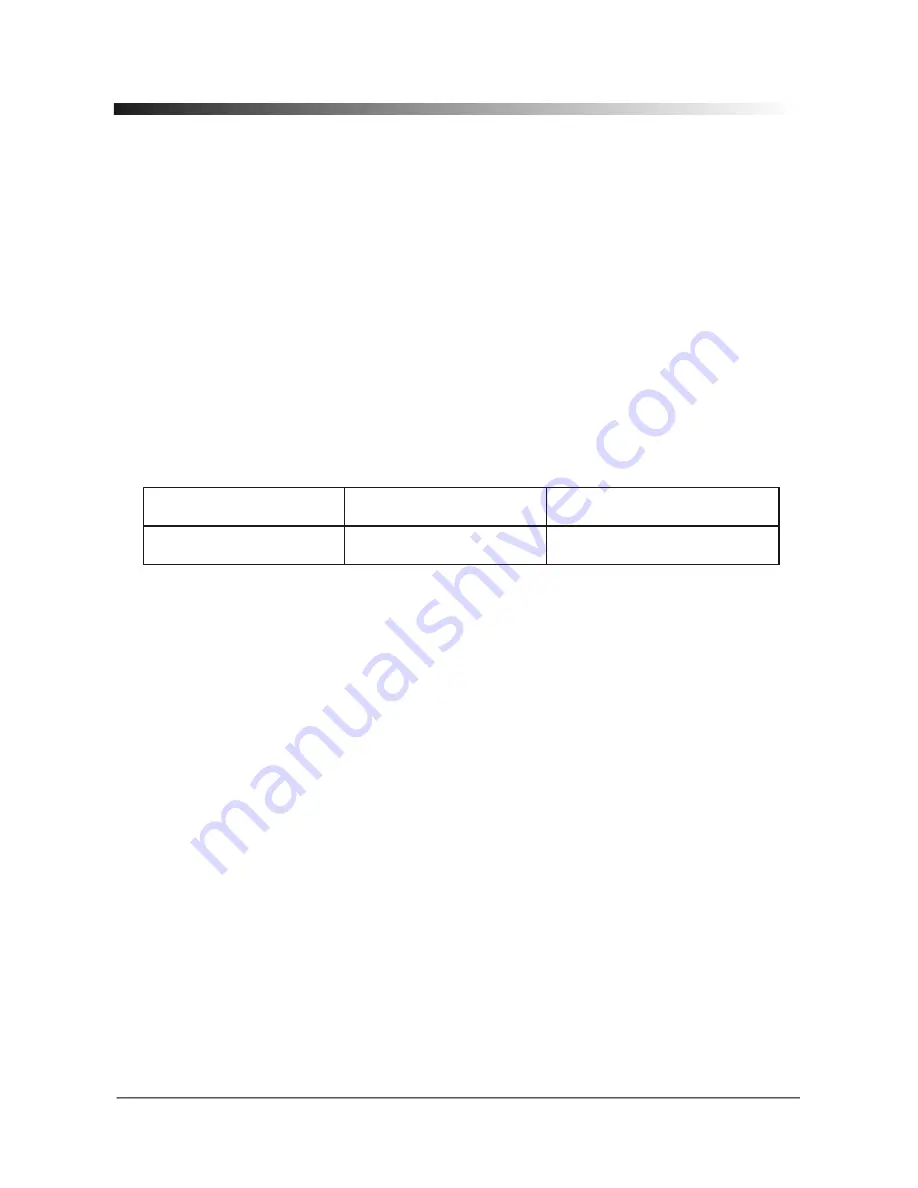
Referring  to  the  Fig  E,  here  following  the  table  showing  the  relation  between 
the  THR/VAR  potentiometer  position  on  the  Grid  and  the  Sub  Harmonic 
Synthesizer Amount in terms of Gain Amplitude at 65Hz

Atk/Rel Select Led

Atk/Rel Confirm Led Pot's related Parameter

ON

OFF

SUB HARMONIC

16

Summary of Contents for CLP-160

Page 1: ...19 482mm DIGITAL USB...

Page 2: ...Instructions Page 2 Controls and Parameters Page 3 RMS Compressor Notes Page 4 Sub Harmonic Synthesizer Notes Page 5 Input and Output Level Considerations Page 6 8 RMS Compressor Page 9 14 Sub Harmoni...

Page 3: ...nit Refer all servicing to qualified service personnel To prevent the risk of shock do not attempt to service this equipment yourself because opening or removing covers may expose you to dangerous vol...

Page 4: ...On Off RMS Compressor Active Bypass Pot Input Level Analog Input Gain Left Right Pot Output Level Analog Output Volume Left Right TECHNICAL DATA Inputs Balanced 2 TRS 2 XLR Outputs Balanced 2 TRS 2 X...

Page 5: ...signal of a Unit in order to maintain the amplitude of the OUTPUT signal at a defined level when input level is exceeding a defined intervention Threshold The Compressor implemented in the CLP160 is...

Page 6: ...pression smoothly before the Threshold In addition to the RMS Compression process in the CLP160 is also available a powerful Sub Harmonic synthesizer The Sub Harmonic Synthesizer is working generating...

Page 7: ...hat are the Max Absolute Input level which cannot be exceeded without getting an Op Amp clip no longer recoverable by any Digital operation In order to help the user in understanding clearly the follo...

Page 8: ...the unit which is the one before the clipping of the Op Amps in front of the A D converters need to make sure that no Digital clip DSP process is occurring The output will never clip unless the clip i...

Page 9: ...Max Output GND Floor Noise 9 8dBu 90 3dBu 100dBu Analog Bypass de pressing the On Off Process button the Analog Bypass can be activated In this condition the CLP160 is bypassing the Digital section a...

Page 10: ...l Potentiometer set to 7 with reference to the Fig B Any different condition on the Input Signal can bring to the same output results if the Input Level Potentiometer will be Adjusted in order to be c...

Page 11: ...erence to the Fig D picture The following table describes the relation between the Encoder position and the RMS Compression Ratio and Knee type HARD White Area the Knee of the RMS Compressor is HARD t...

Page 12: ...k Rel Select and Atk Rel Confirm buttons TAB 1 Where the Led can be turned On or Off with a simple pressure or made Blinking or Un blinking maintaining them pressed for at least 3 seconds The RMS Comp...

Page 13: ...g a 0dBu Output level as Maximum Output Level the Table relating the Threshold and the Output Level is TAB 2 THR VAR Pot Threshold set at MAX 0dBu Bypass Grid 9 Grid 8 Grid 7 Grid 6 Grid 5 Grid 4 Grid...

Page 14: ...osition on the base of the following Table and considering the Threshold set at 17dBu and the Input level going from OFF to 0dBu TAB 3 THR VAR Pot Threshold set at MAX 200ms Grid 9 Grid 8 Grid 7 Grid...

Page 15: ...tion on the base of the following Table and considering the Threshold set at 17dBu and the Input level going from 0dBu to 20dBu TAB 4 THR VAR Pot Threshold set at MAX 1 7sec Grid 9 Grid 8 Grid 7 Grid...

Page 16: ...nics on the low frequencies can help in improving the quality of the background music and to gain a heavier or more vibrant sound The Sub Harmonic Synthesizer is a process synthesizing the first lower...

Page 17: ...e music that much sought after punch The Sub Harmonic Synthesizer is working on the base of a single control used for deciding the amount of Sub Harmonics in terms of Amplitude Gain To access the Sub...

Page 18: ...lip Led blinking IMPORTANT NOTE Once the CLP160 is configured by the user in all its parameters when the unit will be turned OFF the all values of the parameters will be retained and recalled when the...

Page 19: ...China Office 4 5Floor Building B No 885 Shenzhou Road Science City Guangzhou China Tel 86 20 62845258 59 60 Fax 86 20 62845256 Http www marani com cn MAINS...

Reviews: