background image

-15-

   Rightside Tool Bar

   Downside Tool Bar

1. Ima

ge pl

ay mode

There 

a

re three ki

nds of

 pl

a

y

 mode,p

review picture w

ould be d

ispl

a

yed 

ac

c

o

rding t

requir

eme

n

ts such as 

“device list

” , 

origina�on char

t

” 

and 

channel 

t

ou

r

”,d

e

fault mode is 

“device list

” ,ho

wever user needs 

t

o

 c

o

n

figu

re “

origina�on


char

t


and

 “

chann

el t

ou

r


rstly

,

then it w

or

ks

.

2. 

P/T/Preset/T

our/

Tr

ack

Ope

r

a�on m

e

thod is almo

s

t the same, please 

re

f

er t

o pan and �le 

c

o

ntr

ol func�on i

ntr

oduc�on on 3.3.3.7

1. 

Previe

w split mode                                        ,select p

revie

w split mode 

b

y y

ou

rsel

f.

2. 

T

our 

swit

ch and i

nt

ernal �me                        ,

t

our i

nt

ernal �me 

w

ould 

be 1se

c

ond, 2se

c

ond,5 se

c

ond,10 se

c

ond and self

-de

fine �me.

3. Lin

k

a

ge preview swit

ch          ,if enable lin

k

a

ge preview swit

ch,and 

trigg

er alarm,p

review pictur

e of alarm channel 

w

ould be pushed 

t

current preview inter

face.

4. 

F

ace 

rec

ogni�on        ,

t

o click face 

rec

ogni�on bu�on 

t

o e

nter 

face 

r

eal �me 

c

omparison i

nter

face,user 

c

an see 

r

eal �me 

c

a

ptured 

pictur

e,namely 

c

ompa

red 

face pictu

r

es,

re

f

er t

o follo

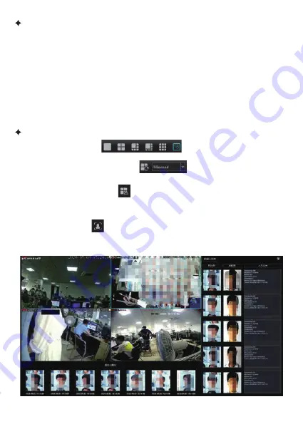
wing picture:

Summary of Contents for AI NVR

Page 1: ......

Page 2: ...n 3 3 1 Start Se ng 3 3 2 How to connect IPC to IVR 10 Charpter 3 Host Opera on 3 1 Boot And Shutdown 3 1 1 Boot 3 1 2 Shutdown 3 1 3 Power Off Recovery 09 Charpter 2 Installa on Guide 2 1 HDD Installa on 04 2 1 1 Front Panel Introduc on 2 1 2 Product Overview 05 2 2 Statement 2 3 Install Hard Disk 2 3 1 Hard Disk Installa on Steps 06 2 4 Network Connec ng Diagram 07 Charpter 1 Product Introduc on ...

Page 3: ...arm Management 50 3 3 5 5 Disk Management 52 3 3 5 6 Network Management 67 3 3 5 7 System Configura on 71 3 3 5 8 System Maintance 74 3 3 5 9 Network Diagnosis 76 Charpter 6 FAQ 80 Charpter 4 Network Opera on Guid 77 Charpter 5 Cellphone Opera on Guid 78 3 3 5 1 2 Face Search 33 3 3 5 Advanced Se ng 3 3 5 1 AI Se ng 3 3 5 1 1 Face Recogni on 25 3 3 4 Channel Connec on 24 3 3 3 7 PTZ Control 22 ...

Page 4: ...ral devices to one power adapter overload may cause over hea ng or a fire hazard 4 Please make sure that plug is firmly connected to the power socket 5 If smoke odor or noise rise from the device turn off the power at once and unplug the power cable and then please contact the service center Warnings Serious injury or death may occur if any of the warnings are neglected Cau ons Injury or equipment da...

Page 5: ...he same or equivalent type only Dispose of used ba eries according tothe instruc ons provided by the ba ery manufacturer Disconnect the power from the IVR before installing a hard disk drive HDD Factory recommended HDD should be used for this installa on Step 1 Remove the cover from the IVR by unfastening the screws on the back and side Step 3 Install HDD in the HDD rack using the provided screws ...

Page 6: ...Hard drive Status Indicator HDD LED is normally blue indica ng that the device is func oning properly USB USB2 0 Interface Universal Serial Bus USB ports for addi onal devices such as USB mouse and USB Hard Disk Drive HDD 1 This equipment is a digital video surveillance product specially designed for the security field By using the embedded LINUX opera ng system to enable the system to operate more...

Page 7: ...e all to prevail in kind 1 The IVR with more than 9 channels must access the gigabit switch otherwise there will be a loss of video or stands ll phenomenon 2 All the IP addresses of the network devices in lan cannot conflict 3 The gateway needs to be set by right IP address 2 2 Statement Note Need to prepare a cross screwdriver This series of IVR can be installed in the case with 1 to 24 hard disks...

Page 8: ...power of device should be turn off and disconnect power supply The device model with a hard disk box supports hot swap 2 4 Network Connec ng Diagram General NVR connec on mode AI NVR and IPC can be connected in the same LAN through switches as shown in the figure ...

Page 9: ... S N POE NVR Camera 52V Power Supply 15M Network Cable 4CH 1PC 4PCS 1PC 4PCS 8CH 1PC 8PCS 1PC 8PCS Connec on mode of POE NVR just connect IPC to the POE power supply port of NVR through network cable as shown in the figure ...

Page 10: ...r off and automa cally restore to the working state before power on to con nue working Insert the power line press the power switch on backboard and then press the switch bu on on the front panel to boot the recorder The video output is the default for the mul image output mode If the boot me be in the me of recording which preset before the system will automa cally start the ming recording func on...

Page 11: ...g IVR user needs to know how to connect IPC to IVR The device support mul version ONVIF protocol is compa ble with famous brand IP Camera such as following brand Before IPC network camera is connected to IVR please ensure that IP address and IVR are the same network segment and the main stream and sub stream need to be adjusted to the recommended value Otherwise maybe user can not search IPC no im...

Page 12: ...rch automa cally all IPC connected to LAN user can add them to rela ve channel according to requirement moreover under condi on that user know IP address port parameters click on address bar to input rela ve parameters then save it it also add channel refer to step 3 3 4 To take real me preview video recording playback channel connec on and advanced configura on for example to introduce IVR main fu...

Page 13: ...nt shortcut func on on each bar moreover there are some hided shortcut func on now introduce them one by one All configura on interface exist on this tool bar under it is not hided 1 Channel audio volume switch user can adjust volume through slider 2 Real me alarm light when alarm occurs light would be flash a er click indicator it will display detailed alarm informa on refer to following picture ...

Page 14: ... service it will display P2P APP download QR code and device series QR code device online situa on device series refer to following picture A er clicking detailed informa on on interface it would be switched to AI cloud video interface user can inquiry rela ve detailed informa on 4 Network Informa on the device network rela ve informa on would be displayed a er clicking it and diagnose and configur...

Page 15: ...a er clicking it will display brightness chroma contrast saturability user can configure it by self defined 6 System informa on icon system informa on hard disk informa on and recording informa on would be displayed a er clicking it refer to following picture ...

Page 16: ...same please refer to pan and le control func on introduc on on 3 3 3 7 1 Preview split mode select preview split mode by yourself 2 Tour switch and internal me tour internal me would be 1second 2second 5 second 10 second and self define me 3 Linkage preview switch if enable linkage preview switch and trigger alarm preview picture of alarm channel would be pushed to current preview interface 4 Face ...

Page 17: ...ll channels on preview interface To choose one channel and drag it to another channel system will push tool p there are three kinds of exchanging channel mode 1 Swap channel connec on all configura on exchange 2 Swap channel sequence exchanged preview posi on device list informa on would be changed 3 Swap window posi on exchanged preview posi on device list informa on would be not changed When user...

Page 18: ... parameter se ng An bond Menu An bond menu basically includes shortcut func on keys men oned above on preview interface under non full screen and full screen user can operate it according to personal usage habit refer to following picture Real me Preview Face Recogni on Result 1 To click face recogni on on preview interface user can enter face real me comparison interface and see real me compariso...

Page 19: ...imilarity name number descrip on channel name list style and me refer to following picture There is hidden tool bar at the downside of each channel it would appear when mouse slide to downside click bu on progress bar would be appeared 3 3 3 2 Real me Playback ...

Page 20: ...in playback mode default mode is local recording interface like following picture System already choosed CH1 CH16 on channel list by default user can choose inquiring recording channel according to origina on chart Default me is date of the day user can choose date search style and method then click inquiry bu on on interface to find rela ve recording recording situa on would be displayed on blank ...

Page 21: ...ng scale according to playback accuracy playback me pos on would be accurate Name Icon Func on Pause Play Pause or play recording Stop Stop playing recording Forward Backward Forward backward recording according to me Single frame play Play recording in frame Forward backward 30S Forward backward recording 30S Slow Fast Play recording by the speed of 1X 2X 4X 8X 16X Split mode Switch playback spli...

Page 22: ...ick bu on to mark pictures in the process of playing This module is to visit the files in the USB external storage device inserted into the IVR and all the backup files can be searched in this module 1 Click bu on system will line up them according to me 2 System will mark singal picture a er selec ng it in icon user can click bu on to operate marked pictute in list by choose all cancel selected inv...

Page 23: ...nder right corner can delete the selected files The camera of PTZ could be controlled to move to 8 direc ons up down le right upper le upper right upper right and lower right magnifica on and reduc on of the mes enlargement and narrowing of the focal length the enlargement of the aperture and the narrow lt speed se ng lights wipers fan and other func ons As the figure shown below 1 Firstly rotate the...

Page 24: ...ct the serial number click Change to camera will move to the corresponding preset posi on 1 Enter the cruise se ng interface 2 Double click the blank areas that beside the corresponding No to select the preset point name then click Se ng and pop up window enter the cruise name click Add cruise and select the preset point in the drop down box to set cruise speed and residence me and the max cruise ...

Page 25: ...hes IVR will sequence IP address of camera searched by system to select many ip cameras to add them in batches 4 Add all add all searched IP cameras to IVR 5 Export configura on export system configura on to external storage device connected to IVR by USB 6 Import configura on import system configura on file in external device into IVR it would be valid a er restar ng device 7 Plug and play Enable or d...

Page 26: ...Modify groups modify groups name name list style and linked channel 3 Delete groups delete created groups 4 Import groups import face picture in batches 5 Export groups The packet informa on in the device can be exported to the current selected group or all created groups 6 Capture picture quality user can select the quality of the imported face image now there are original picture super high defin...

Page 27: ...k the le mouse bu on on the upper le corner of the image hold it and drag it to the lower right corner release the mouse a er the target face image is in the box select the corresponding face template on the right and click extract face 3 A er the face template extrac on is completed add the name number and descrip on on the face template image and then click OK In the corresponding groups you can...

Page 28: ...box select the corresponding face template on the right and click extract face 7 A er the face template extrac on is completed add the name number and descrip on to the face template image and then click OK to view the face template image informa on in the corresponding group 8 If you are not sa sfied with the current effect you can click delete face to delete the extracted face template image and t...

Page 29: ... completed 14 At this me user can see the imported face image in the group Note The total number of imported faces including all groups is determined by the model of the product and also related to the quality of the imported image The clearer the picture the less the number of imported faces 1 A er clicking the synchroniza on group the synchroniza on mode selec on box would be pop up There are di...

Page 30: ... capture IP camera and face comparison IP camera if user needs to realize this func on must choose one of them 2 Enable turn on or off face detec on func on 3 Sensi vity the Higher the sensi vity the higher the accuracy it is harder to detect faces 4 Pixel of minimum picture system will detect face s pixel which is more than or equal to the minimum pixel ranges from 16 to 300 pixel 5 Quality of cap...

Page 31: ... on the face The default is 40 8 Face expansion coefficient height The size of the captured image generated by the extending outward height on the basis of the face the default is 85 9 Scene image upload Set whether to enable the func on of uploading the scene image it is not selected by default 10 Interval me check face interval me 11 Scene Image Quality 1 99 the larger the number the be er the qua...

Page 32: ...g area overlap the detec on area the shielding area would be priority 14 Linkage Type There are three types of name lists white name list black name list and other list Click bu on of the arming and user can set arming me on configura on interface user can use the copy func on to set the arming me to be the en re week or me period of one day of one week A er finishing se ng user click OK to save ref...

Page 33: ...displayed in the alarm informa on column of the local device d Upload center The alarm informa on will be real me displayed in the device s Web terminal or pla orm alarm informa on bar 2 Alarm output A er the device is connected to alarm output device if the alarm is triggered the alarm informa on will be feedback to the alarm output device 3 Local preview linkage user can select one channel sever...

Page 34: ... the alarm is triggered device would be linked to preset of the PTZ device cruise ot track to alarm or click cancel to cancel all linkages A er se ng the linkage mode click OK to save 1 User can choose channel me period and search type according to different search types refer to following picture 2 User can search selected face pitcure again on searched picture interface refer to following picture...

Page 35: ...cture and recording to select backup pictures or recording click the Backup bu on to back up the pictures or recording to the memory disk refer to following picture 5 The searched pictures would be displayed in list user can query 10 second recording and backup on list interface method same as above refer to following picture ...

Page 36: ...ognized face picture from white name list 10 Other name list search user can query the captured face pictures that are not in the black name list and white name list that is the unrecognized face pictures 11 Local name list search According to face list search in the local face template of the device user can query the face pictures of which similarity value is more than or equal to the set value ...

Page 37: ...manually draw a frame on the page and the extracted face will appear in the face template on the right If the extracted face template is not good user can delete the face and start to draw frame to extract face again and finally click search refer to following picture The func on of this page is to configure the relevant parameters when the moving objects which is larger than the propor on cross the...

Page 38: ...means flow sta s cs result A B count number B A count number ignore namely traffic sta s cs result A B count number 4 Propor on Only when the propor on of the moving object in the screen exceeds the set size the moving object would be regarded as target When se ng a yellow do ed rectangle as a size reference will appear in the center of the screen 5 Traffic sta s cs A er enabling user can set the traffic...

Page 39: ...ross line vehicles is 201 between at 10 00 15 30 which exceeded the threshold of 200 and triggered the target count alarm The above picture is real me picture when the alarm occurs The func on of this page is to configure relevant parameters if me of objects le or loss is more than set detec on me for the objects which are larger than the propor on alarm will occur The following describes how to se...

Page 40: ... loss or object le behind 3 Propor on Only when the propor on of moving objects on the screen exceeds the set size the moving objects would be regarded object 4 Detec on me When me of object loss le behind exceeds set me system will trigger alarm According to the above se ngs the Propor on of moving objects on the channel is more than 150 when the moving objects disappear more than 30s in the dete...

Page 41: ...riggered un l Object leave monitoring area 2 Object Enter When object enter into monitoring area from other areas 3 Object Leave When object leave from monitoring area 4 Object Enter or Leave Object enter into monitoring area or leave from rela ve area 5 Object wander Object wander in the se ng area 6 Propor on Check object propor on on picture 7 Detec on Time detec on me is valid only for wander ...

Page 42: ...se audio linkage trigger electronic fence detect alarm will link to alarm and broadcast rela ve hint sound 13 Alarm light Choose alarm light a er triggering electronic fence detect alarm informa on it will link to alarm light output 14 A er finish se ng parameters click save bu on it would be valid The func on of this page is to configure the relevant parameters when the moving objects which is larg...

Page 43: ...rs detec on line would flash alternately in red or blue blue frame would track moving object a er moving object cross detec on line 1 Only IP camera support this func on 2 Support to detect sta c and dynamical human shape of monitoring area 3 Advise to set accurate humanoid size range according to different usage scene it will make detec on faster and reduce wrong detec on Humanoid detec on configura...

Page 44: ... to humanoid quality grade threshold value 5 Set Detec on Area Press mouse key to click area which would be drawn on picture of channel whatever direc on user hold mouse right key to move to it will create red frame if se ng is not good user can erase it and reset it shielding area se ng is same with this Note if shielding area is overlapped on detec on area it would be priority please refer to fo...

Page 45: ...olygon min support triangle a er drawing area it will extend one arrow can turn 360 degree to choose direc on a er confirm direc on then loose mouse key then click save if client draw wrong line can clear it then restart again The center point of area is default A point another side is B point when people walk from A to B point it will trigger retrograde alarm 5 Erase draw line click erase to clear...

Page 46: ...ser can set rules and detec on result whether are displayed in real me preview as above picture 4 Se ng Area To use mouse to click area which would be drawed on channel s picture press mouse le key to extend to draw line it will create one pcs turning line for each click mouse right key end to draw it will create a closed area like above picture blue imaginary line is object propor on size 5 Erase...

Page 47: ... etc 1 Local Channel Name name in red typeface would be displayed on le corner of picture and is modified 2 Channel Name name channel as marks and synchronize with IP camera 3 Time Date format can choose different me date format on appointed channel 4 Image Se ng can set brightness contrast satura on chrome for appointed channel 5 OSD Se ng the names of channels and dates are marked as yellow rectan...

Page 48: ... down list the default is full frame rate 6 Image quality When the bit rate type is variable bit rate different image quality can be selected according to requirement 7 I frame interval The usual I frame interval is 25 The resolu on of local snapshot pictures and the interval me of snapshots can be set for each channel of the device The func on of se ng the organiza onal structure is to preview cha...

Page 49: ...ding the current channel system will only perform recording opera ons 2 Timing recording it is only during the se ng ming recording period that the current channel system will perform recording opera ons 3 Alarm recording it is only when the alarm recording func on is triggered that the current channel system will perform recording opera ons 4 Stop recording the current channel stops recording imm...

Page 50: ...urn on ming and alarm recording func ons 1 Manual capture of single or mul ple channels can be turned on 2 Can turn on or off the ming capture func on Click File Backup to enter the file backup interface The main interface of default backup se ngs is shown in following picture This product supports the backup download of recording and picture files The following describes the backup condi ons 1 Chann...

Page 51: ...nforma on will be automa cally displayed in Storage Loca on U Disk Total Capacity and U Disk Remaining Space A er all the above condi ons are met click the bu on in the lower right corner of the file backup interface to view the backup status from the changes in the Backup Progress bar The backup is completed when the progress reaches 100 1 Detec on mode the default is front end detec on when the d...

Page 52: ...on alarm func on The se ng method is similar to the mo on detec on s se ng When the painted area is blocked an alarm will be triggered Please note that the channel connected by the onvif protocol does not support the blocking alarm func on 1 Select the channel and alarm status 2 Enable the alarm processing func on default is not enabled 3 Arming me linkage mode select the me period of arming and l...

Page 53: ... and stop recording the default is automa c coverage 2 SMART processing There are two types ignore the error and con nue recording and stop recording when error occurs 3 Recording Keep Time Max up to 4 SMART informa on Click the icon to pop up the SMART informa on list of the current hard disk 5 Lost alarm If the current sata port is not connected to the hard disk missed hard disk alarm informa on...

Page 54: ... ons 2 2 Protocol select IPSAN protocol 2 3 Network hard disk IP address Input IP address of network hard disk server the device IP address must be in the same network segment with the server address 2 4 Network hard disk directory A er selec ng the network hard disk to be created the address directory of the network hard disk will be displayed 2 5 Advanced se ngs port user name and password are d...

Page 55: ... on the interface click OK and the interface shows that it is dele ng 2 For a while the informa on of the network hard disk in the list is cleared and the hard disk informa on is no longer displayed on the preview interface In the advanced configura on alarm management system abnormality select network hard disk disconnec on and the trigger mode is selected by audible alarm monitor alarm upload cen...

Page 56: ...test recording will be retained 4 Support mutual rota on between network hard disk and local hard disk If the device is connected to mul ple hard disks such as a local hard disk and a network hard disk at the same me and the processing a er the recording is full is set to be automa c coverage the recorded hard disks can jump to each other a er the local hard disk or the network hard disk is full 5...

Page 57: ...a icon enable quota the device disables quota by default allocate available capacity to the corresponding channel click OK the corresponding channel will record within the available capacity if the recording is full the previous recording is automa cally deleted and the latest recording is retained ...

Page 58: ...r stop recording It should be noted that when the recording channel of the device exceeds 32 channels and the device is connected to mul ple hard disks in order to ensure the efficiency and performance of the hard disk it will record to 2 hard disks by default and record to one hard disk in the first 32 channels of the recording channel The remaining channel will record to another hard disk Currently...

Page 59: ...cording will not be performed at the me ch7 ch9 ch16 ch64 the ungrouped hard disk is a free hard disk and no data will be wri en Disk1 0 0 Important note When performing manual grouping opera ons the historical video data in the hard disk may be cleared Please be cau ous when opera ng to avoid irreversible losses 3 3 5 5 4 Advanced Configura on Select enable RAID click Save user needs to restart th...

Page 60: ...reate various types of arrays or configure arrays with one click etc 1 One key configura on The RAID5 type array is created by default and the array is named A er clicking OK all the hard disks connected to the device will be created as a RAID5 array by default and the hot spare disk will be automa cally allocated according to the number of hard disks connected Up to two disks can be allocated as Ho...

Page 61: ...s on the storage management page A er selec ng the array that needs to be forma ed click the format bu on interface as shown below A er the forma ng is completed the one click configura on of the array is completed and there are automa cally created arrays and hot spare displays on the physical disk and array interfaces ...

Page 62: ...RAID0 RAID1 RAID5 RAID6 and RAID10 Click Create Array name the array select RAID0 type select at least two hard disks and click OK RAID0 At least two hard disks are required to be created and the array capacity is the sum of the two hard disk capaci es ...

Page 63: ...d disk that needs to be used as a hot spare A er clicking the hot spare bu on the hard disk type becomes a hot spare disk When the hard disk in the array fails the hot spare The spare disk can replace the failed hard disk to back up data to avoid data loss click Delete to cancel the hot backup func on of the hard disk Click Create Array name the array select RAID1 type select at least two hard dis...

Page 64: ...K Click Create Array name the array select RAID6 type select at least four hard disks and click OK It is also necessary to format the hard disk A er forma ng the created array can be seen on the array interface as shown in the figure below RAID5 Create at least three hard disks or more and the array capacity is the number of hard disks n 1 RAID6 At least four hard disks are required to create and t...

Page 65: ...en on the array interface as shown in the figure below Click Create Array name the array select RAID10 type select at least four hard drives and click OK RAID10 At least 4 2 n disks are required to be created the array n 0 and the array capacity can only use half of the disk capacity or less ...

Page 66: ...the physical disk interface the hard disk status will be restored to ordinary disk Rebuild A er clicking Rebuild the interface will display the name and type of the current array and the disks in the array Choose one of the ordinary disks of the device as a supplementary hard disk Do not unplug the hard disk during the reconstruc on process to avoid data loss If the hard disk in the array is damag...

Page 67: ...the device If there is a hard disk failure in the array it will be used as a replacement disk to back up data Support for reconstruc on A er the hard disk in the array is damaged the addi onal hard disk can be rebuilt and restored in the array Background task speed refers to the recovery speed of data reconstruc on or hot backup when the array fails Different speeds can be set including high speed ...

Page 68: ...e corresponding SATA hard disk 1 Network card choose different network card types according to needs 2 Physical address display the physical address of the current network interface which is not modified 3 Automa cally obtain IP address the DHCP func on When it is turned on the IP mask gateway cannot be set If the current DHCP takes effect it will obtain the new IP mask gateway assigned by the router...

Page 69: ... func on 1 Server type There are 14 types in the default list 2 Server domain name each server type corresponds to the exis ng default server domain name 3 Port Each server type corresponds to the default port 4 User name password manually enter the correct user name and password 5 Device domain name manually enter the correct domain name a er the func on is OK the domain name can be used to remot...

Page 70: ...ailbox and a relevant prompt will pop up if it is successful It should be noted that the use of the Email linkage func on requires a good network environment and the equipment can access the external network smoothly This page is the ac va on interface of the pla orm protocol The WebServer protocol is enabled by default suppor ng the remote login of the device and other services are enabled as nee...

Page 71: ...erver connec on status display the status of the device registered to the server 7 Auto p2p version the built in autop2p version of the device 8 Auto upgrade version the built in autop2pupgrade version of the device 9 QR code address mobile APP download address Android and Apple device ID number This module supports HTTP face push func on the interface is as shown below 1 Enable Whether to enable ...

Page 72: ...ime zone switch the me zone the page will pop up the new date and me and some me zones have the summer me func on 5 NTP me calibra on A er the func on is enabled user needs to click the bu on to synchronize the network me the device needs to access the external network 1 Manual me adjustment manually click the me adjustment bu on to perform me adjustment opera on inside 2 Automa c me adjustment wh...

Page 73: ... on The local display resolu on of the IVR can be modified display support is required and it will take effect immediately a er modifica on 0 minutes 1 Channel informa on display There are 4 display modes the preview interface device list is refreshed in me a er the modifica on is successful 2 Real me playback me There are 5 me op ons which will take effect immediately a er modifica on 3 Video stream mo...

Page 74: ...nabled by default all configura on boxes below are grayed click the enable bu on the resolu on bit rate type bit rate upper limit and video frame rate below can be configured A er configura on click to save as shown in the figure 2 Channel configura on the channels that can be set to zero channel are displayed on the le and the screen number can be controlled on the right Select a split screen in the r...

Page 75: ...ently accessing IVR 4 Telnet se ngs whether to enable Telnet On this page user can query different types of logs according to different types and me The main types of logs include opera on abnormal and alarm Each type corresponds to mul ple sub types the system defaults to query All types of logs log me can be cross day query as needed There are five func on bu ons on this page and each bu on has a d...

Page 76: ...ade opera on is performed on this page The USB port of the IVR needs to be inserted into the external storage device with the product update file A er selec ng the file click Upgrade A er the upgrade is completed the device needs to be restarted Note During the upgrade process please do not perform any opera ons on the local and remote terminals to avoid irreparable errors There is only one op on of...

Page 77: ... normal or not as shown in the figure below Network test 1 PING test This func on can test whether the data transmission status between the current network and the device or server you want to connect to is normal as shown below 2 Packet capture test some devices have dual network cards and you can choose the network card freely as shown in the figure below ...

Page 78: ... respec vely If there is no rou ng device in the network please assign an IP address in the same network segment If there is a rou ng device in the network you need to set the corresponding gateway and subnet mask Please refer to System Se ngs Network Parameters for the network se ngs of the network digital video recorder 3 Please make sure that the IP address is set correctly A er the IP address ...

Page 79: ...correctly user can enter the network preview interface For details on the opera on method of the network terminal please refer to the host terminal This opera on guide is an instruc on on how to install and use the mobile client on Android and iOS mobile phones The mobile client APP commonly used for using our products is Cloud Eye AI The mobile client so ware supports Android 4 0 and above system...

Page 80: ...func ons of frequently used bu ons are as follows Func on bu on Name Func on details Add device Select the QR code to scan the ID number to add a device Capture Snap a picture of the current channel the picture file is saved to the default photo directory of the phone by default Manual recording Manually record the current channel the recording file is saved to the default mobile phone s recording d...

Page 81: ... panels please choose 01 02 05 etc 5 IVR IP address conflict 1 Please check whether the ba ery in the remote control has been installed correctly especially the posi ve and nega ve polarity 2 Please check if the ba ery in the remote control is s ll charged 3 Check whether the remote control window is covered 4 Please check whether the remote control address of the NVR matches the remote control add...

Page 82: ... network digital video recorder 3 Please check whether there is an IP conflict in the network 1 The player is not installed correctly 2 The file system of the U disk or mobile hard disk used for backup is wrong 3 The graphics accelera on so ware of DX9 0 or above is not installed 1 My se ngs of mo on detec on alarm occlusion alarm and video blocking are correct but why not Because your IPC uses the ...

Page 83: ...company s i8 protocol and the interna onal ONVIF protocol 5 There is a video prompt for an image and there is an image a er double clicking but there is no image in the mul channel preview Right click on that channel click Remote Configura on in the menu that comes out there is a mode drop down menu op on in the middle try to adjust the main stream to the sub stream and then save If there is s ll n...

Page 84: ...MAPESEN TECHNOLOGY LIMITED www mapesen com 0086 755 89345865 info mapesen com ...

Reviews: