Manley Stingray iTube Owner'S Manual Download Page 16

REMOTE CONTROL

Your Stingray iTube is equipped with a Remote Control that communicates with the amplifier via RF (radio frequency) and/

or IR (infrared) signals. In the Stingray iTube’s Menu Mode, you can alter these transmission settings (to learn how to do that, 

see page 9). RF signals can pass through walls, so now you can operate your Stingray iTube from Anywhere In Your House!! 

We’re finally catching up with the last century.

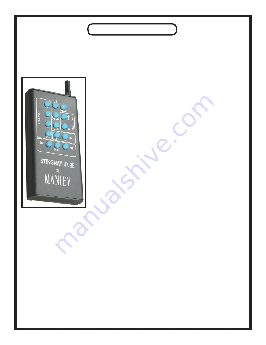
This Remote can control almost all functions of your Stingray iTube. As seen in the picture below, the following functions are 

available:

Inputs: 1, 2, 3, & iPod. On the Stingray iTube’s faceplate, LEDs around the Input Se-

lection knob display the selected Insert.

Standby: Pushing the top-center button puts the unit into Standby mode, and wakes it 

up if pressed again. In Standby mode, no audio comes through the unit - no high volt-

ages are present, no glowing tubes, etc.

Mute: Be Gone, Beautiful Music! Thou art Silenced! While the Stingray iTube is 

muted, a blue LED will pulse at 6:00 on the Volume/Balance knob.

Volume: LEDs around the Volume/Balance knob display the current volume.

Balance: LEDs around the Volume/Balance knob display the current balance only in 

Balance Mode. See page 9 for details.

Insert: This switches the Loop Return On or Off (the REC OUT output is always ac-

tive). When this button is pressed, the Stingray iTube looks for signal at the Loop 

Return rather than at the selected input. When Loop Return is on, an LED at 1:00 on 

the Input Selection knob glows red.

DIM: Lowers volume to a predetermined level. See page 9 for details. 

iPod Controls: Previous, Play/Pause, & Next

Note: When the Stingray iTube is recieving signal from the remote (every time one of 

the remote’s buttons is pressed), a red LED will momentarily illuminate at 2:00 on the 

Input Selection knob. If the Stingray iTube’s remote has dead batteries, this red light 

will NOT flash, and the remote will NOT function.

Another note: To pair a “universal” remote with your Stingray iTube, the supplied Manley remote control must AL-

READY have been paired to the Stingray iTube. For reference, the IR “carrier” frequency for the Stingray iTube is 

38kHz, which is standard for many universal remote controls.

FCC INSTRUCTION TO THE USER

This equipment has been tested and found to comply with the limits for a class B digital device, pursuant to part 15 of the FCC 

Rules. These limits are designed to provide reasonable protection against harmful interference in a residential installation. This 

equipment generates, uses and can radiate radio frequency energy and if not installed and used in accordance with the instruc-

tions, may cause harmful interference to radio communications. However, there is no guarantee that interference will not occur 

in a particular installation. If this equipment does cause harmful interference to radio or television reception, which can be 

determined by turning the equipment off and on, the user is encouraged to try to correct the interference by one or more of the 

following measures:

* Reorient or relocate the receiving antenna.

* Increase the separation between the equipment and receiver.

* Connect the equipment into an outlet on a circuit different from that to which the receiver is connected.

* Consult the dealer or an experienced radio/TV technician for help.

In order to maintain compliance with FCC regulations, shielded cables must be used with this equipment. Operation with non-

approved equipment or unshielded cables is likely to result in interference to radio and TV reception. The user is cautioned 

that changes and modifications made to the equipment without the approval of manufacturer could void the user’s authority to 

operate this equipment.

16

Summary of Contents for Stingray iTube

Page 1: ......

Page 2: ...THE STUFF ON THE SIDES 7 8 DETAILED FRONT PANEL FUNCTIONS 9 DISPLAY MODES 10 OPTIMIZING YOUR SOUND SYSTEM 11 12 TUBE F A Q 13 14 ALL YOU NEED TO KNOW ABOUT BIAS 14 15 REMOTE CONTROL 16 iPod S VIDEO o...

Page 3: ...gant and practical Visual beauty may be a prime factor for some but the size shape and component locations were chosen first for performance reasons Please take a few moments to read through this manu...

Page 4: ...he Waste Electrical and Electronic Equipment Directive The purpose of the Direc tive is the prevention of waste of electrical and electronic equipment and to promote the reuse and recycling and other...

Page 5: ...ired type or slide the loop that holds the pair together If you need to connect a turntable vinyl you will need a separate phono preamp to raise the level from the tiny signal from the cartridge to re...

Page 6: ...ise decreases it Push in the knob for 2 seconds and release it to enter Balance Mode To exit Balance Mode push and quickly release the knob For more information on these functions see page 9 NOTE The...

Page 7: ...n the input select switch will appear here So you can plug this Recording output into a Tape Deck or CD Recorder or Computer Sound Card analog input to make recordings from whatever is playing and sel...

Page 8: ...nd what you are looking for We do not suggest you play with this switch all the time You should never switch up and down rapidly as there are high voltages on this switch and you ll blow something up...

Page 9: ...er than the others Again the Volume Balance knob adjusts the gain in this mode The range of gain adjustment runs from 12dB in the fully counterclockwise LED position to 11dB fully clockwise Default is...

Page 10: ...brightness 3 Starlight Mode Settings Speed 11 00 LED lit Only functional when Display Timeout is selected When the display times out this mode will make the LEDs twinkle in a mostly random sequence I...

Page 11: ...The angle of the tweeter or speaker front panel to your face is also critical and experiment with that too You should be getting a smooth frequency response so that highs and lows are balanced and mi...

Page 12: ...with plain painted gypsum walls and hardwood floors The simpler the decor the more intense the acoustic problems The only hints we can offer is that the wall behind the speakers and behind you are of...

Page 13: ...d and in selecting that tube that will work really well for your piece of gear we probably had to throw away several In some cases we might have had to go through 30 tubes to find the quietest one or...

Page 14: ...ower tubes in our amplifiers after a few years if you notice a small revolt going on where several of the output tubes are misbehaving or getting hard to bias you might consider doing a full re tube K...

Page 15: ...above 3 or below 2 then you may be seeing a tube begin to go bad Watch it for a while or check it every few weeks noting changes This tube should be replaced probably With mains changes all the tubes...

Page 16: ...tarily illuminate at 2 00 on the Input Selection knob If the Stingray iTube s remote has dead batteries this red light will NOT flash and the remote will NOT function Another note To pair a universal...

Page 17: ...s towards 0 minutes When time is up the volume will fade out slowly then the unit will go into Standby Sweet dreams iTube iPod S Video oMy First a thought from Manley Laboratories The integration of a...

Page 18: ...be the Stingray iTube In that case the two most likely problems are a bad tube 12AT7 or 6414 or a blown 250 mA MDL 1 4 B fuse accessible through the sides of the unit See page 8 for details on chang...

Page 19: ...oice a cup of coffee She was describing a new integrated amplifier she wanted to build and proceeded to make one of those legendary bar napkin drawings Gordon remarked It looks like a stingray the fis...

Page 20: ...Kohm nominal Optimum Speaker Load 5 ohms Actual Output Impedance at 20Hz 2 36 ohms at 1KHz 2 ohms at 20KHz 1 83 ohms Output Z Headphone Output 53 ohms Damping Factor 2 4 Scratch Factor Use pennies und...

Reviews: