


RATED CAPACITY LIMITER
OPERATOR MANUAL NBT60XL
7-18
Published 11-01-2020 Control # 710-00
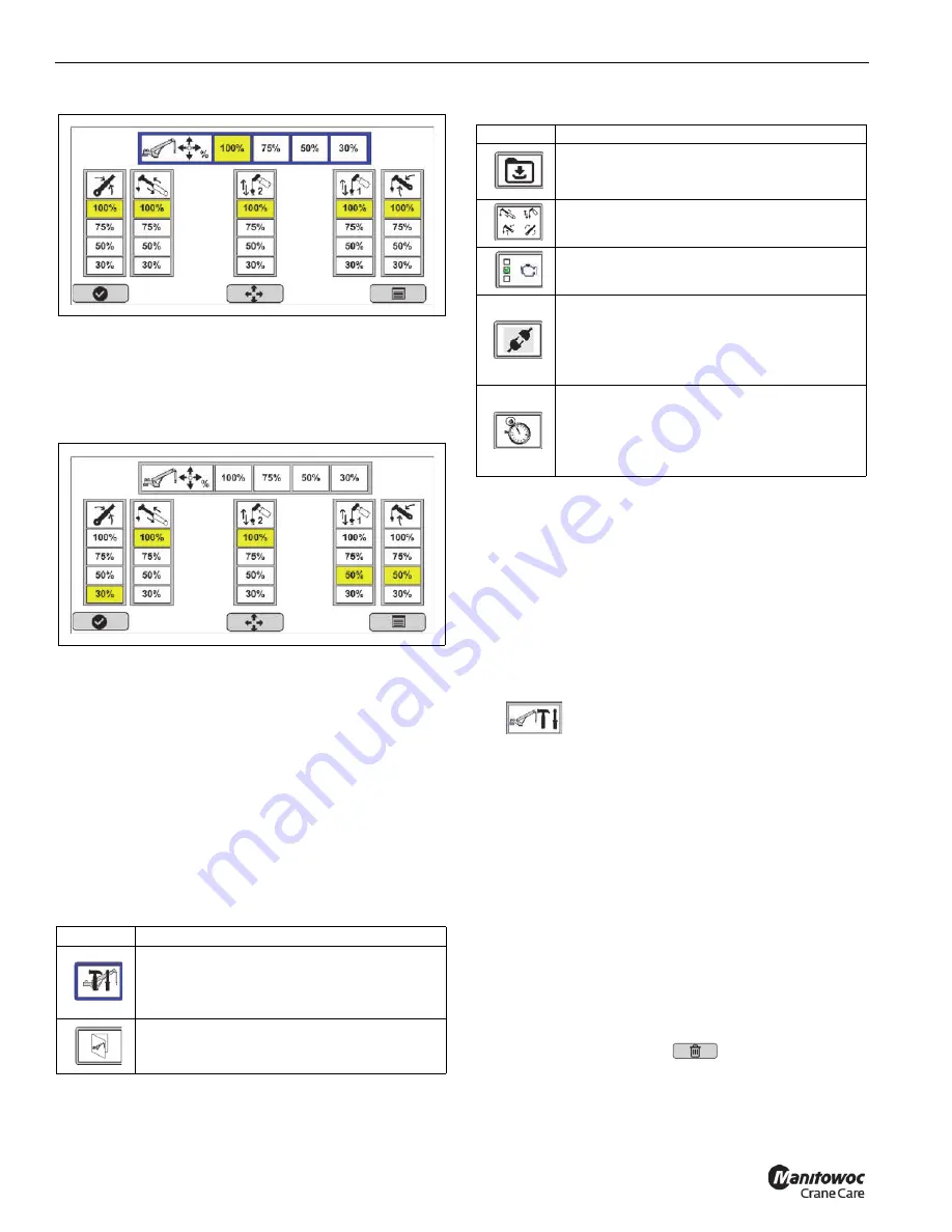
Joystick Output #2
•
The operator can also set the desired output for each
function as shown in Joystick Output #3 screen.
Using the arrow keys select the new percentage using
the vertical bar. The new value turns yellow indicating it
is the current value, Joystick Output #3 screen.
Joystick Output #3
•
When a Joystick value is not set at 100% (default
standard), the RCL Operating Mode screen (page 7-4)
identifies the non-standard setting in the upper left hand
corner next to the general error icon. For more
information about the different icons, see Table 7-3.
•
Values are saved when the machine is shutdown.
SYSTEM CONFIGURATION
Use the following procedure to access the System
Configuration Menu. The System Configuration menu is
where the functions shown in Table 7-10 can be accessed.
Accessing the System Configuration Menu
Use the following procedure to access the System
Configuration menu. The password 12331 is required to
continue to the System Configuration Menu.
1.
In the main menu, select the Tools icon.
The Tools menu appears.
2.
In the Tools menu, select the System Configuration icon
.
3.
Enter the password 12331 to continue to the System
Configuration menu. For more information, see
“Entering the System Configuration Password” on page
7-18.
Entering the System Configuration
Password
A 5-digit password is required to access the system
configuration screen. After three failed attempts, there is a
three second timeout before the user can re-enter the
password. After all numbers are entered, the Select button
turns green.
The up and down indicator in the time and password boxes
correspond to button (4) “OK” to modify selection.
Use the Delete functional key
to remove all entries.
The System Configuration screen is where you calibrate the
sensors, upload the RCL software, and load charts.
Table 7-10 System Configuration Menu Icons
Icon
Description
Sensor Calibration Menu
— Select this icon
to calibrate crane sensors. This icon appears
red if sensors need to be calibrated. For more
information, see the
Service Manual
.
Enable Chart Loading
— Select this icon to
upload a new load chart. For more
information, see the
Service Manual
.
8807-38
8807-39
Software Update
— Select this icon to load
software updates. For more information, see
the
Service Manual
.
Crane Function Configuration
— For more
information, see the
Service Manual
.
Truck/Engine Configuration
— For more
information, see the
Service Manual
.
Component Addressing
—Select this icon
to update or add a CAN bus address to a
component. This icon appears red when
components need to be addressed. For more
information, see the
Service Manual
.
Real-Time Clock Configuration
— Select
this icon to update the RCL system time and
date information. For more information, see
“Setting System Date and Time” on page 7-
19.
Table 7-10 System Configuration Menu Icons
Icon
Description
Fo
r
Reference
Only


