


Grove
Published 01-14-2021 Control # 707-01
8-61
TMS9000-2 SERVICE MANUAL
CARRIER
8
delivery and exhaust ports on both modulators are identified
with a cast, embossed numeral for positive identification.
Acceptable Tire Sizes
The speed calculation for an exciter ring with 100 teeth is
based on a default tire size of 510 revolutions per mile. This
figure is based on the actual rolling circumference of the
tires, which varies with tire size, tire wear, tire pressure,
vehicle loading, etc. The ABS response sensitivity is reduced
when the actual rolling circumference is excessive on all
wheels. For a 100 tooth exciter ring, the minimum number of
tire revolutions per mile is 426, and the maximum is 567.
The ECU will set diagnostic trouble codes if the number of
revolutions is out of this range. In addition, the size of the
steer axle tires compared to the drive axle tires also has to
be within the ABS system design. To avoid diagnostic trouble
codes, the ratio of the effective rolling circumference of the
steer axle, divided by the effective rolling circumference of
the drive axle, must be between 0.85 to 1.15.
ABS Troubleshooting
Diagnostic Connector and ABS Diagnostic Switch
Location
The 9–pin on board diagnostic connector (1), (Figure 8-64) is
located under the dashboard to the left of the steering
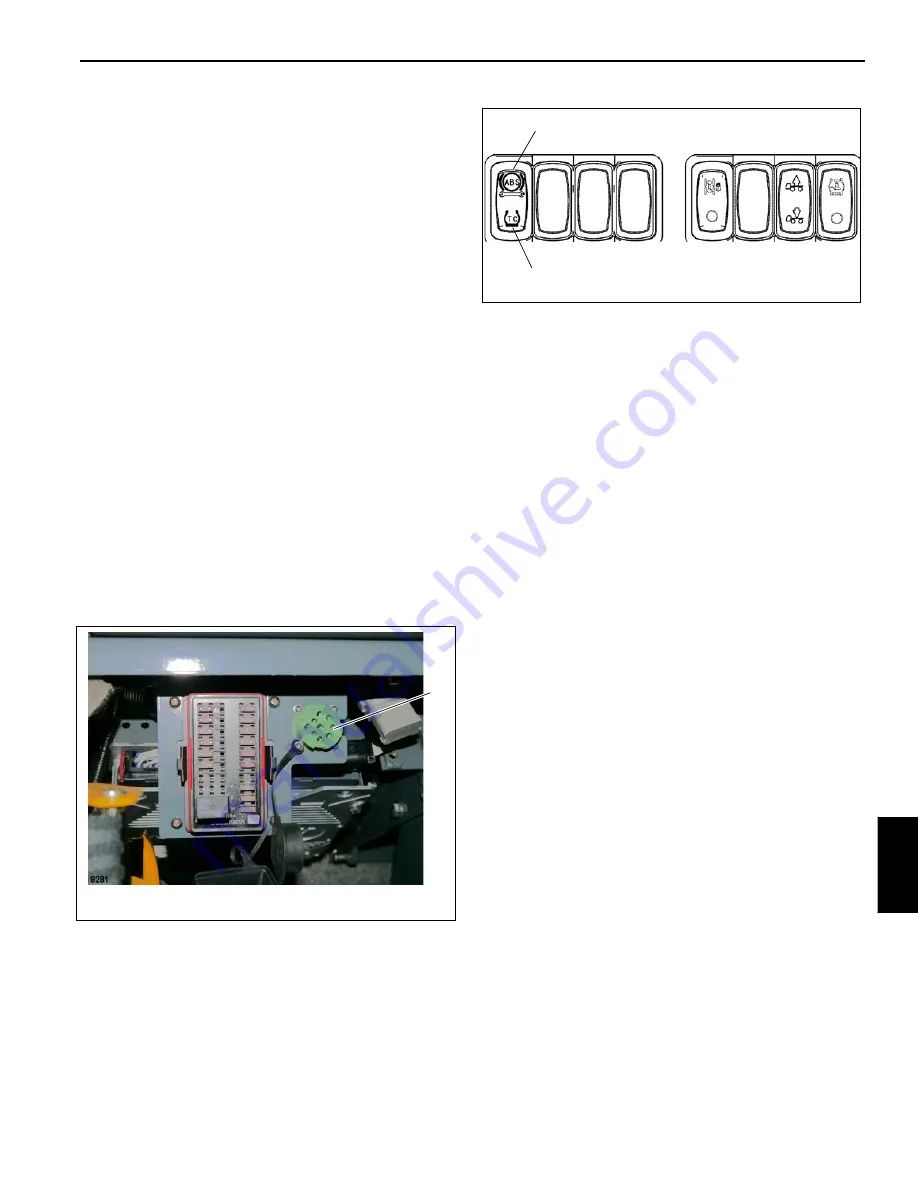
column. The ABS diagnostic switch (1), (Figure 8-64) is
located near the lower left of the control panel as shown in
(Figure 8-65).
The ABS ECU is located at the rear of the cab behind the
driver’s seat. The ABS wiring harness is combined with the
main cab and engine harness.
Troubleshooting: Blink Codes and Diagnostic Modes
The EC-60 controller (ECU) contains self-testing diagnostic
circuitry that continuously checks for the normal operation of
internal components and circuitry, as well as external ABS
components and wiring.
ECU Diagnostics
Active Diagnostic Trouble Codes
When an erroneous system condition is detected, the EC-60
controller:
1.
Illuminates the appropriate indicator lamp(s) and
disengages part or all of the ABS and ATC functions.
2.
Places the appropriate trouble code information in the
ECU memory.
3.
Communicates the appropriate trouble code information
over the serial communications diagnostic link as
required. Hand-held or PC-based diagnostic tools attach
to the vehicle on board diagnostic connector, located
under the left-side dash.
NOTE:
When using a hand-held device such as the Bendix
RDU or Pro-Link refer to the manual that came with
the device.
Blink Codes
Blink codes allow a technician to troubleshoot ABS problems
without using a hand-held or PC-based diagnostic tool.
Instead, information about the ABS system is communicated
by the ECU using the ABS indicator lamp to display
sequences of blinks.
NOTE:
The ECU will not enter the diagnostic blink code
mode if the wheel speed sensors show that the
vehicle is in motion. If the ECU is in the diagnostic
blink code mode and then detects vehicle motion, it
will exit the blink code mode.
FIGURE 8-64
1
9281
FIGURE 8-65
1
2
9288
r
Reference
Only


