DEALER SERVICE ADDENDUM
INTRODUCTION
When servicing the fork, take the time to
inspect all parts for excessive wear or damage. There are basically
three aspects of a fork that will require attention:
1.
Lubrication of stanchions (inner legs) and bushing inspection
2.
Spring stack
3.
Damping system
LUBRICATION OF STANCHIONS (INNER LEGS) AND
BUSHING INSPECTION
The outer leg bushings need to be serv-
iced approximately every 40 hours of riding (depending on conditions
– extreme conditions may require a more frequent service schedule).
The method used to determine if your fork requires the lubrication
system to be cleaned and serviced is if stiction (binding as you com-
press the fork) develops. If you feel any stiction, remove the inner
legs per the instructions below and inspect the bushings for signs of
excessive wear. Pay close attention to the bushing contact surface,
which can be damaged by contamination in severe conditions.
Replace any worn or damaged parts that are discovered.
SPRING STACK
Inspection and service of the spring stack should
be performed after 80 hours of riding. The spring stack may require
servicing if there is an audible rubbing sound coming from the left
side of the fork during compression. The spring stack can be removed
and serviced using the instructions below.
DAMPING SYSTEM
The damping system on your DORADO fork
needs to be serviced approximately every 40 hours. The DORADO fork
uses a sealed gas free hydraulic damping system. The damping oil
and foam compensator (if installed) should be removed at this time
and replaced with 5WT fork oil as described in the instructions below.
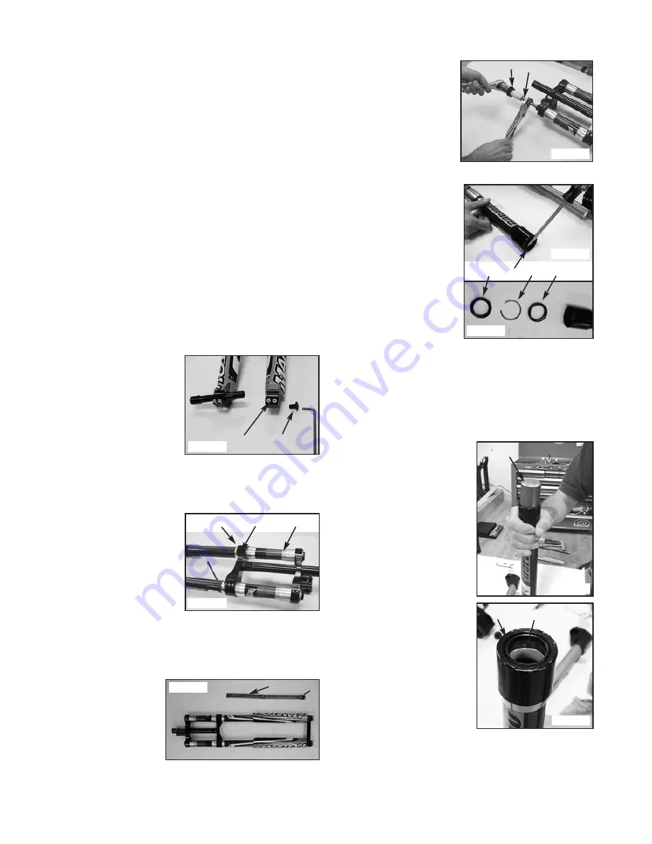
Hex Axle – Removal (Figure 1)
To remove the front wheel,
loosen the four dropout pinch
bolts (1) using a 5 mm hex
wrench. Loosen the button head
screw (2) on the right side of
the fork (while facing the fork)
using a 6 mm hex wrench. Push
the axle through the dropouts
from right to left.
Hex Axle – Installation
Reverse the steps above. Torque the button head screw to 15–20 in.-
lbs. (1.7–2.3 Nm). Torque the pinch bolts to 40–45
in.-lbs. (4.5–5.1 Nm).
Triple Clamp Removal (Figure 2)
Loosen the five pinch bolts (1)
using a 4 mm hex wrench and
slide the outer leg down through
the assembly.
Triple Clamp Installation
(Figure 2)
Wipe the aluminum sleeves (2)
on the outer legs and inside of
each triple clamp (3) with iso-
propyl alcohol. Position the
lower clamp on the flat surface
of the leg sleeves; the inside of the clamp must have full surface con-
tact with the sleeve. Torque the pinch bolts to 60–75 in.-lbs. (7.3–8.5
Nm).
Coil Spring Removal (Figure 3)
Use a 20 mm socket to remove the bottom right leg (facing the fork)
end cap (1). Pull the spring
stack (2) consisting of
one MCU, two springs and
connectors out of the
fork leg.
Coil Spring Service, Ride
Kit Installation (Figure 3)
Replace the spring in the
sequence shown, coating
the spring with a liberal amount of Maxima spring grease. Install the
end cap. Torque the end cap to 60–70 in.-lbs. (6.9–7.90 Nm).
Inner Leg Removal (Left Leg, Figure 4)
Remove the coil spring (see above) prior to removing the compression
rod. Unscrew the top cap (1)
with a 1 1/16" socket. Pull the
shaft out of the inner leg until it
stops; do not force. Clamp the
shaft using soft jaw blocks
(Answer tool P/N 064615). Using
a 1 1/16" socket, unscrew the top
cap off of the compression rod
(2). Pull the inner leg downward
from the outer leg.
Seal System Removal and
Bushing Replacement
(Figures 5 and 6)
There are two seals that make up
the sealing system on the bottom
of the outer carbon legs: an outer
(dust) seal to prevent contamina-
tion from the outside, and an
internal (oil) seal to retain lubri-
cation grease inside the fork. The
seals should be replaced if exces-
sive grease is found to be leaking
out of the fork or if on inspection,
excessive contamination is found
inside the outer leg. The seals
must also be removed if it
becomes necessary to replace the
bushings.
Remove the outer (dust) seal (1)
as shown (2). Pry out the metal circlip (3) and then the lower (oil)
seal (4). Discard both seals and circlip; they cannot be reused once
removed.
The bushings should be inspected for signs of wear (discoloration) or
tears on the surface. Bushings can be replaced using tools and
instructions found in Answer bushing removal and installation tools
PN 85-3909 and 85-3911.
Seal System Installation (Figure 7 and 8)
The two seals must be identified and
oriented before installation:
1.
The oil seal is installed first
and is rubber on the outside
diameter. It is installed so that
the lip is pointing to the inside
of the outer leg. Install using
Answer seal installation tool
P/N 064000 (1).
2.
Install the circlip into
the machined groove in the
outer leg.
3.
The dust seal is installed last
and has metal on the outside
diameter. It is installed so that
the lip is pointing to the out-
side and metal surface towards
the circlip. Use the installation
tool to tap the seal into place.
The dust seal will be flush with
the rim (2) of the outer leg
when the seal system installa-
tion is complete.
Before reinstalling the inner leg
after servicing, liberally apply
Motorex grease to the upper and
lower outer leg bushings (3). Lightly
grease the inner legs before inser-
tion.
1
2
1
3
2
2
1
FIGURE 3
1
2
FIGURE 2
FIGURE 1
FIGURE 4
1
2
3
4
FIGURE 5
FIGURE 6
1
2
3
FIGURE 7
FIGURE 8
Summary of Contents for DORADO DH
Page 1: ......


