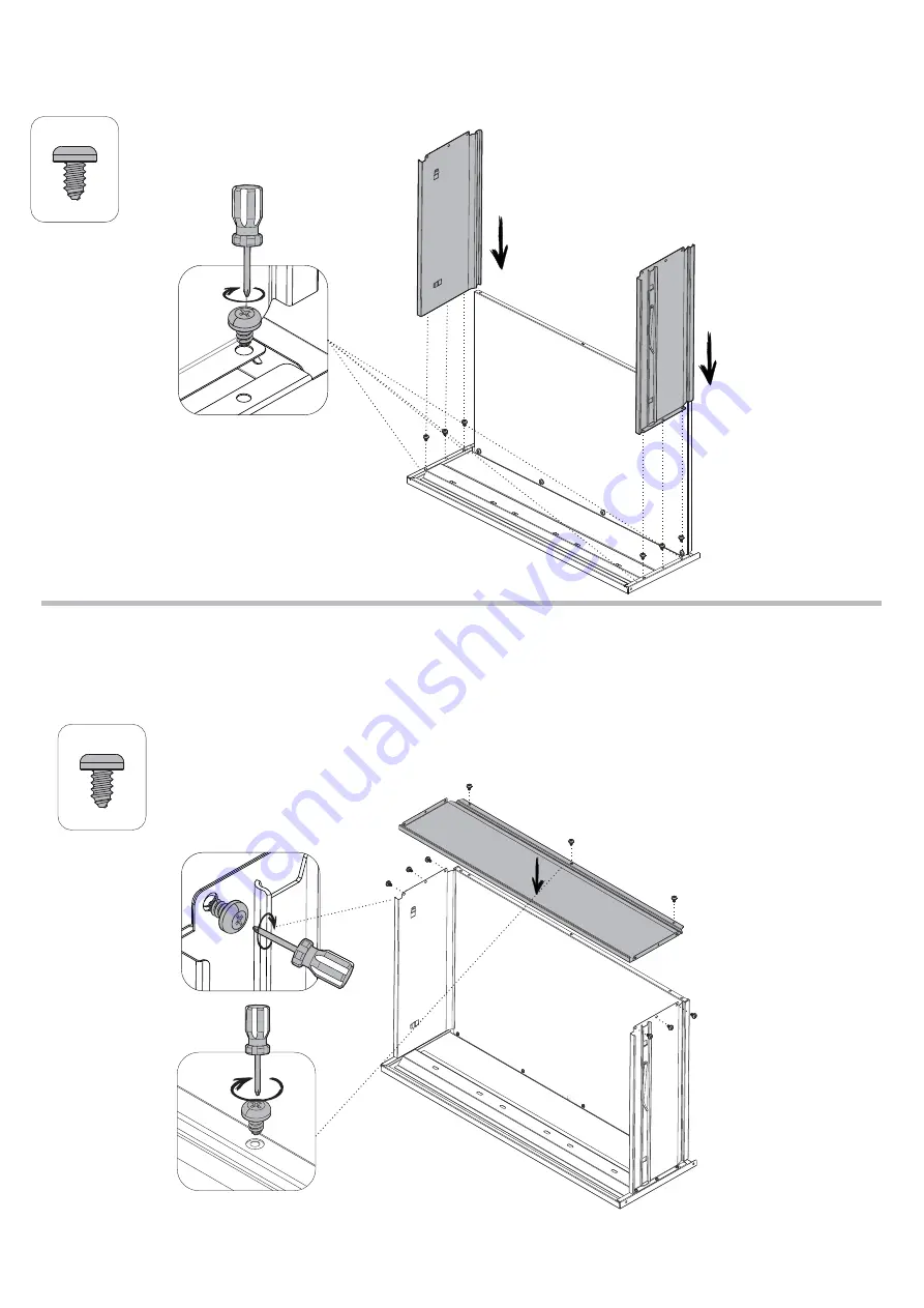
Manhattan Comfort 2GMCC Assembly Manual Download Page 10

6x

F18

9x

F18

1 - Align parts 

P12

 and 

P13 

on 

     part 

P15 

and slide to part 

P28

.

2 - Screw the two parts with 

F18.

STEP 13

STEP 14

1 - Insert part 

P14

 over part 

P15

 and 

     between parts 

P12

 and 

P13

.

2 - Then, fix part 

P14 

to parts 

     P12, P13

 and 

P15, 

with 

F1

.

8

P13

P15

P28

P12

P15

P13

P28

P12

P14

Summary of Contents for 2GMCC

Page 1: ...Stuck Questions We are here to help 1 888 230 2225 help manhattancomfort com 1000009893 21 12 2021 Assembly Guide Model 2GMCC Fortress 31 5 Mobile Garage Cabinet With Drawer And Shelves...

Page 2: ...the assembly you should separate and identify the parts first Necessary hardware for the assembly Stuck Questions We are here to help 1 888 230 2225 help manhattancomfort com IMPORTANT In order to avo...

Page 3: ...STEEL UN P3 LEFT SIDE 3000007341 3000011875 3000011961 STEEL 1 UN P5 TOP 3000007369 3000011874 3000011960 STEEL 1 UN P7 BOTTOM 3000008643 3000011848 3000011935 STEEL 1 UN P9 LOWER BACK 3000007266 300...

Page 4: ...ontal side with F1 and F2 1 Fit part P7 inside part P3 2 Fit both parts in the frontal side with F1 and F2 STEP 2 STEP 1 4x F2 4x F1 P7 P3 4x F2 4x F1 P7 P3 P2 2 1 2 1 WARNING Do not tighten the screw...

Page 5: ...STEP 3 1 Turn the cabinet with the back side upwards 2 Fit parts P2 and P3 to parts P5 and P7 with F1 and F2 4x F2 4x F1 8x F2 8x F1 P7 P3 P5 P2 P7 P2 P5 P3 180 180 P7 P2 P5 P3 1 2 3 WARNING Check th...

Page 6: ...he bolts until locked STEP 6 STEP 5 1 Fit part P10 into parts P2 P3 and P5 Check that all fits are supported over the bolts 2 After fitting the parts screw the bolts until locked WARNING Position part...

Page 7: ...n the frontal side of the cabinet 1 Turn the cupboard so that it will stand in the position of use 2 Fix F7 to parts P2 and P3 as shown here below 4x F7 2x F10 2x F11 16x F2 16x F1 P7 P5 P2 P3 P7 P5 P...

Page 8: ...in the figure here below 3 Lower the other side of part P19 leaning it over the left F7 STEP 10 F7 P7 P5 P2 P3 P19 P7 P7 P5 P2 P3 P17 P19 2x F2 2x F1 1 2 1 Fit the lower part P17 in diagonal position...

Page 9: ...bushing fixed in part P7 Then pull down the pin of door P26 upper hinge align the door and release the pin to fit the bushing fixed in part P17 2 Repeat the step for part P27 STEP 12 1 Fit part P15 in...

Page 10: ...13 on part P15 and slide to part P28 2 Screw the two parts with F18 STEP 13 STEP 14 1 Insert part P14 over part P15 and between parts P12 and P13 2 Then fix part P14 to parts P12 P13 and P15 with F1 8...

Page 11: ...1 Fit the drawers already assembled between parts P2 and P3 through the drawer slides 2 Check that the drawer slides on both sides are properly fitted If they are not properly fitted the drawer will n...

Page 12: ...ing the limited warranty period 7 Damage resulting from improper loading beyond the specified maximum weight capacity outlined in the assembly instructions provided with the product including overload...

Reviews: