


mangOH Yellow Hardware Architecture Guide
Rev 2 Oct.19
28
41113116
The RTC provides basic functionality (provides clock (year, month, day, weekday, hours, minutes, seconds) and
calendar), and includes a clock output signal (CLKOUT) that connects to a buzzer (
) for user-defined
purposes.
2.4.15 Buzzer
The mangOH Yellow includes an integrated buzzer (U406) for user-defined use. The buzzer is activated by the
RTC clock output signal (CLKOUT).
2.4.16 Expansion Connector
The mangOH Yellow provides a 15-pin expansion connector (CN805) that can be used to connect an external
device to the mangOH Yellow. The expansion connector includes several pins that connect to the CF3 module’s
signals as detailed in
Note: All signals (pins 2–14) are 3.3 V.
For additional information, including default configuration and how to temporarily change it, see
Connector Interfaces on page 35
.
Important:
Do not use the UART connections on both the IoT card (
) and a device via the
expansion connector to the mangOH Yellow at the same time.
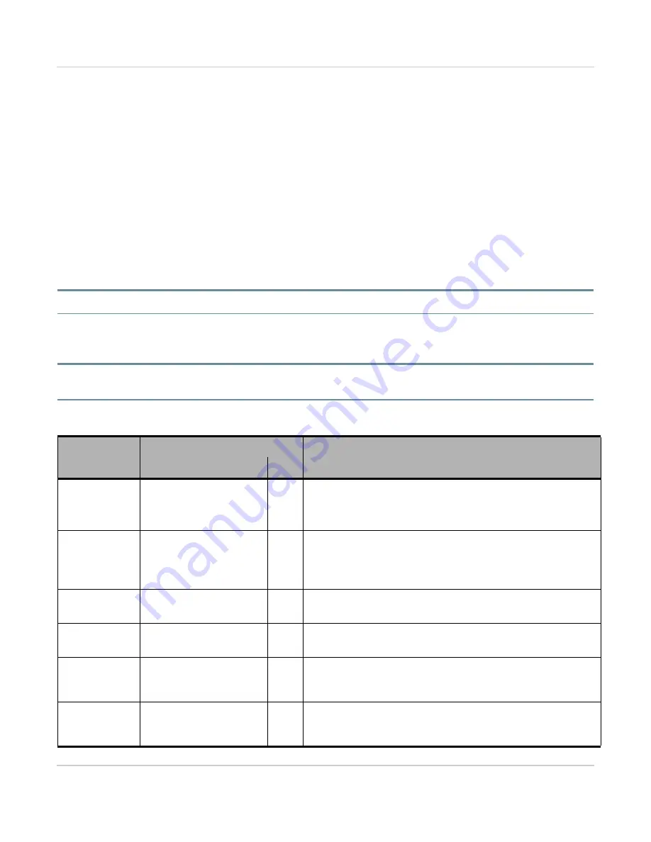
Table 2-6: Expansion Connector Signal Connections to CF3 Module
Expansion
Pins
CF3/Other Signal(s)
Notes
Signal
Mux
Output Power
(Expansion to
mangOH Yellow)
(Pin 1)
VIN_CONN
n/a
Purpose: Connected device provides power to the mangOH Yellow
when Power Supply Selector (CN801) jumper is on pins 2–3.
For details, see
Reset
(Pin 2)
SYSTEM_RESET via:
•
LOWPOWER_RESET
(CF3 GPIO6)
•
Reset button (SW401)
n/a
Purpose: Input from mangOH Yellow to reset the connected device.
SPI
(Pins 3–6)
HSIC
(Pins 14–15)
No
Purpose: Data transfer; application control
For details, see
HSIC (USB/Ethernet) on page 23
.
UART
(Pins 7–8)
UART1
(Pins 5–6)
Purpose: Data transfer via 2-pin UART interface (Tx/Rx).
For details, see
ADC
(Pin 9)
ADC2
(Pin 107)
No
Purpose: General purpose ADC output to host application (e.g.
indicate when a sensor has triggered)
For details, see
.
I2C
(Pins 10–11)
I2C1
(Pins 1, 66)
Hub
Purpose: Data transfer (standard mode). Higher speeds possible if
supported by host application.
For details, see
.


