background image

Page 59

Version 2022-12-20

SEDM-L - Smoke extraction damper - multi

TPM 157/22

VII. PRODUCT DATA

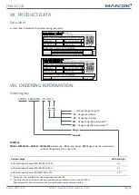
Data label

Data label is placed on the damper casing (example)

VIII. ORDERING INFORMATION

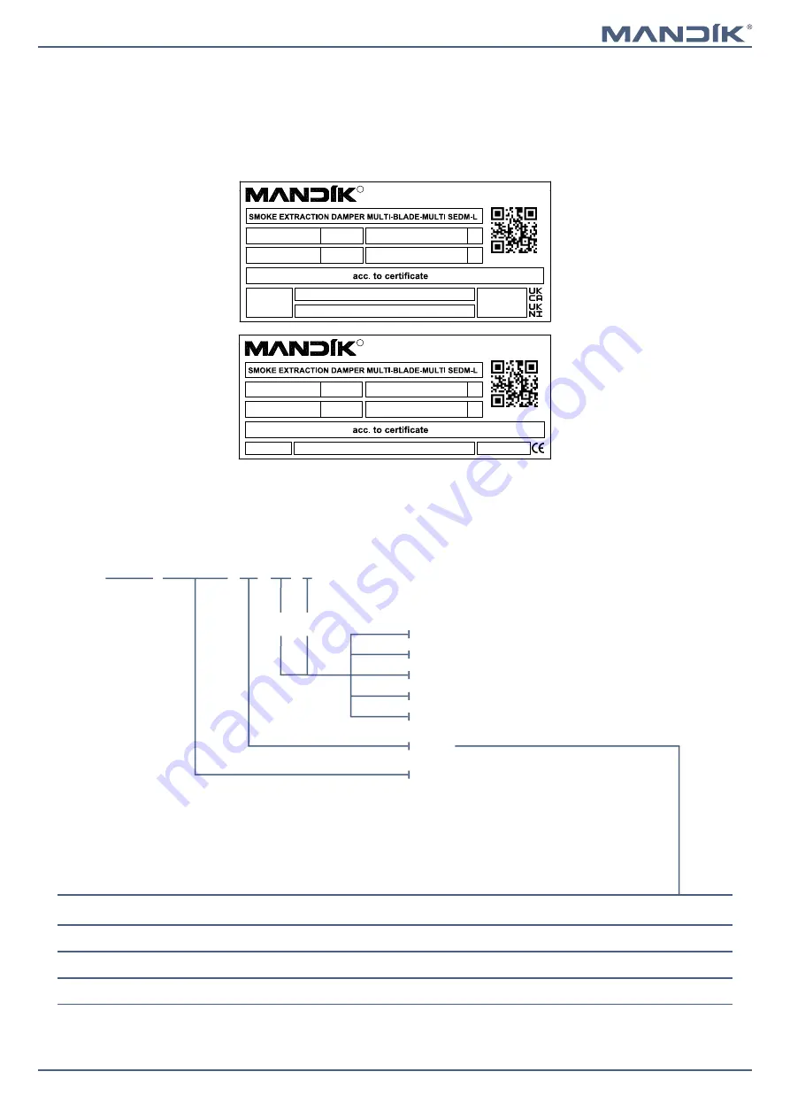
Ordering key

without flange and grille

P1

 - flange over blades

P2

 - flange over damper

M1

 - flange and grille over blades**

M2

 - flange and grille over damper**

SEDM-L   1200x2030 - .44 / M2 / –

EXAMPLE:
SEDM-L 1200x2030 - .44/M2/– 1200x2030

-damper size, 

.44

-damper design, 

M2

-flange and grille over damper,

without flange and grile on right side

design

size AxB

Dampers design

Additional digit

with actuating mechanism BEN, BEE, BE for 230V

.44

with actuating mechanism BEN, BEE, BE for 24V

.54

with actuating mechanism BEN (BEE)-SR for 24V

.65*

Design .65 is not available by using actuating mechanism BE.

**  The surface of the grille is provided with powder coating, standard colour is the RAL 9006.
 

Requirements for other colour must be discussed in advance with the manufacturer.

Right

side

Left

side

WEIGHT (kg):

Dobříšská 550, 267 24 Hostomice, Czech Republic

MANDÍK, a.s.

ACTUATING SYSTEM:

YEAR/SER.NO.:

DIMENSION:

TPM 157/22

R

FIRE PROTEC. CLASS:

MANUAL

Certificate UKCA No.: 0832-UKCA-CPR-P1007, DoP: PM/SEDM-L/02/22/1

EN 12101-8:2011

Certificate UKNI No.: 0832-UKNI-CPR-P1002, DoP: PM/SEDM-L/02/22/1

WEIGHT (kg):

Dobříšská 550, 267 24 Hostomice, Czech Republic

MANDÍK, a.s.

ACTUATING SYSTEM:

YEAR/SER.NO.:

DIMENSION:

TPM 157/22

R

FIRE PROTEC. CLASS:

MANUAL

Certificate CE No.: 1391-CPR-2021/0009, DoP: PM/SEDM-L/01/22/1

EN 12101-8:2011

Summary of Contents for SEDM-L

Page 1: ...ik cz Manufacturer MANDIK UK Ltd 130 Aztec West Bristol BS32 4UB United Kingdom Tel 44 117 4526376 E Mail help mandik co uk Authorized representative SEDM L Smoke extraction damper multi Technical Doc...

Page 2: ...t and Assembly 16 Statement of installations 23 Installation in solid wall in solid shaft wall construction 24 Installation in gypsum wall in gypsum shaft wall construction 26 Installation in battery...

Page 3: ...truction Installation type Classification In a shaft wall of gypsum plasterboard construction which is a part of a smoke extraction duct multi damper in the shaft wall shaft wall th min 100 mm Ablativ...

Page 4: ...ignals e g from smoke detectors The use of cables with a certain fire resistance for the supply voltage ensures that the actuator is supplied even in the event of a fire Ventilation system During vent...

Page 5: ...of the insulated cover box when installing the damper or when connecting the actuator power cable The power and control cable must be Cat 3 as BS EN8519 Design 44 and 54 Belimo modulating actuators B...

Page 6: ...nsioning 6 VA Imax 8 2 A 5 ms 6 5 VA Imax 8 2 A 5 ms 7 VA Imax 4 A 5 ms Protection class III III II Degree of protection IP 54 Adjustment time for 95 30 s Ambient temperature Storage temperature 30 C...

Page 7: ...on IP 54 Adjustment time for 95 60 s Ambient temperature Storage temperature 30 C 55 C 40 C 80 C Connection drive auxiliary switch Cable 1 m 3 x 0 75 mm2 Cable 1 m 6 x 0 75 mm2 BEE 24 ST with plug con...

Page 8: ...x 7 9 A 5 ms Protection class III II Degree of protection IP 54 Adjustment time for 95 60 s Ambient temperature Storage temperature 30 C 55 C 40 C 80 C Connection drive auxiliary switch Cable 1 m 3 x...

Page 9: ...l damper control panel to BS ISO 21927 9 Cable glands Comms cable Damper control module PCB mounted on plastic rail Earth stud 230v 50hz 3A fused supply by others Switches 6 core Drive open close 230v...

Page 10: ...20 TPM 157 22 Dimensions SEDM L without flange and cover grille Thebladespacingisalways200mm SEDM L with flange and cover grille over blades External dimension of the grille The blade spacing is alway...

Page 11: ...amper Flange 2 types External dimension of the grille B B Flange over damper B B Y 30 A B 17 10 10 Flange over blades A A X A A Detail X Detail Y Oval holes in the corners are used to connect the duct...

Page 12: ...on damper multi Page 12 Version 2022 12 20 TPM 157 22 Cover grille KMM The grilles type KMM TPM 002 96 can be used to close smoke control dampers Maximum size KMM can we supply is 2400x2400mm Free are...

Page 13: ...4 2 350 0 1508 56 6 2 5 2 7 1 6 2 2 400 0 1733 58 6 2 6 2 7 1 7 2 3 450 0 1958 60 7 2 7 2 8 1 8 2 4 500 0 2183 62 7 2 8 2 9 1 9 2 5 550 0 2408 64 8 2 9 3 2 2 7 600 0 2633 66 8 3 3 1 2 2 2 8 650 0 2858...

Page 14: ...0 3116 94 9 3 7 3 8 2 6 3 8 BELIMO BEE 25 N m 400 0 3581 98 3 8 3 9 2 8 4 450 0 4046 102 7 3 9 4 3 2 4 2 500 0 4511 107 4 4 3 4 4 4 550 0 4976 110 1 4 1 4 1 3 6 4 6 600 0 5441 113 2 4 2 4 2 3 8 4 9 6...

Page 15: ...350 0 4724 135 8 4 9 4 9 3 8 5 2 400 0 5429 139 9 5 5 4 1 5 5 450 0 6134 144 1 5 1 5 1 4 4 5 8 500 0 6839 148 2 5 1 5 2 4 7 6 550 0 7544 153 5 3 5 2 5 6 3 600 0 8249 157 2 5 4 5 3 5 3 6 6 BELIMO BE 40...

Page 16: ...te in the transport packaging Pay attention to the appropriate length of the forks of the forklift handling equipment to avoid breaking of wooden planks consequently damaging the damper s blades Small...

Page 17: ...2022 12 20 SEDM L Smoke extraction damper multi TPM 157 22 4 Place the damper in the installation hole 5 After installing the damper and possibly hardening the plaster mortar remove the transport str...

Page 18: ...TPM 157 22 6 Ways of placing the flange on the damper 2 types of flanges X The inner edge of the damper aligns with the inner edge of the flange Flange edge Damper edge Y Flange over damper Flange ov...

Page 19: ...n the damper Fix in all holes around the perimeter of the flange 1 SEDM L 2 Flange 3 Blades 4 Screw UNI 4x30 mm included in the flange package 8 Ways of placing the grille on the damper with a flange...

Page 20: ...e handrail on the damper 1 Flange 2 Grille 3 Bolt M6x20 BN 4825 included in the grille package 4 Spacer ring included in the grille package 5 Retaining ring included in the grille package 6 Rivet nuts...

Page 21: ...ation After installing the damper the damper blades must only be opened or closed by operation of the actuator only Installation side by side This is the BS EN1366 2 test standard dis tances They are...

Page 22: ...Smoke extraction damper multi Page 22 Version 2022 12 20 TPM 157 22 Recommended construction openings Construction opening mortar or gypsum Construction opening Ablative Coated Batt system Recommende...

Page 23: ...0MAmulti damper in the wall Ablative Coated Batt EI 120 vew i o S1000CmodHOT 400 30MAmulti 25 damper in the shaft wall which is a part of a smoke extraction duct multi EI 120 ved i o S1000CmodHOT 400...

Page 24: ...ch is a part of a smoke extraction duct multi 4 British gypsum thistle bond 60 or equivalent can by used minimum density 670 kg m 5 Flange 6 Grille Installation in solid wall in solid shaft wall const...

Page 25: ...6 Flange 7 Grille In case of installation damper tightly above the floor must be joint between damper body and floor min 75 mm and must be completely filled with gypsum Each damper must be suitably s...

Page 26: ...backtostudsworkorsteelworkasrequired A 100 A y y y y Z y min 30 mm max 400 mm A A X 100 X 1 SEDM L 2 Gypsum wall construction 3 Shaft wall of a gypsum wall construction which is a part of a smoke extr...

Page 27: ...allation in battery 1 SEDM L 2 Solid wall construction 3 British gypsum thistle bond 60 or equivalent can by used minimum density 670 kg m 4 Overplating strip e g Supalux S th 15 mm 5 Screw UNI 4x40 m...

Page 28: ...mm max 400 mm 1 SEDM L 2 Solid wall construction 3 Ablative Coated Batt e g Firestop Board HILTI CFS CT B 1S 140 50 min density 140 kg m3 Firestop acrylic sealant HILTI CFS S ACR or equivalent 4 Overp...

Page 29: ...joint between damper body and floor min 75 mm and must be completely filled with gypsum Each damper must be suitably supported in each corner front and rear with temporary supports whilst being Insta...

Page 30: ...0 mm 7 M8 bolt assemply bolt M8x105 mm 2 pcs large washer M8 nut M8 In case of installation damper tightly above the floor must be joint between damper body and floor min 75 mm and must be completely...

Page 31: ...ry 1 SEDM L 2 Solid wall construction 3 Ablative Coated Batt e g Firestop Board HILTI CFS CT B 1S 140 50 min density 140 kg m3 Firestop acrylic sealant HILTI CFS S ACR or equivalent 4 Overplating stri...

Page 32: ...psum wall gypsum shaft wall construction Ablative Coated Batt y min 30 mm max 400 mm EIS 120 A A y y y y 100 Z Z X 1 SEDM L 2 Gypsum wall construction 3 Mineral wool type depending on the type of cons...

Page 33: ...ll not prevent free rotation on the blades When installing a flange overplating strip is not installed Seal all joints Overplating strips Spacing strips with SEDM L damper with Promat glue K84 Example...

Page 34: ...on Ablative Coated Batt RESPECT JOINT POSITION Bolts and nuts shall not prevent free rotation on the blades When installing a flange overplating strip is not installed Seal all joints Overplating stri...

Page 35: ...on the blades When installing a flange overplating strip is not installed Seal all joints Overplating strips Spacing strips with SEDM L damper with Promat glue K84 Examples of anchors to the fire div...

Page 36: ...stallation damper tightly above the floor must be joint between damper body and floor min 75 mm and must be completely filled with gypsum Each Damper must be suitably supported in each corner front an...

Page 37: ...1 SEDM L 2 Solid wall construction 3 Ablative Coated Batt e g Firestop Board HILTI CFS CT B 1S 140 50 min density 140 kg m3 Firestop acrylic sealant HILTI CFS S ACR or equivalent 4 Overplating strip e...

Page 38: ...or ner front and rear with temporary supports whilst being Installed and fire stopped final supporters must beinstalledbacktostudsworkorsteelworkasrequired y min 30 mm max 400 mm 3 dampers side by sid...

Page 39: ...n case of installation damper tightly above the floor must be joint between damper body and floor min 75 mm and must be completely filled with gypsum Each Damper must be suitably supported in each cor...

Page 40: ...e washer M8 nut M8 span 200 to 300 mm When installing a flange overplating strip is not installed Seal all joints Overplating strips Spacing strips with SEDM L damper with Promat glue K84 Examples of...

Page 41: ...nd must be completely filled with gypsum Each damper must be suitably supported in each corner front and rear with temporary supports whilst being Installed and fire stopped final supporters must be i...

Page 42: ...M6 6 Installation hols 7 M8 bolt assemply bolt M8x55 mm 2 pcs large washer M8 nut M8 The method of mounting must meet the minimum requirements for attachment in accordance with national regulations Fi...

Page 43: ...m Full drawing of bracket see page 44 5 Screw UNI 6x60 mm 6 Installation hols 7 M8 bolt assemply bolt M8x55 mm 2 pcs large washer M8 nut M8 8 Gypsum grid from C profile Fixing SEDM L to the gypsum wal...

Page 44: ...lement steel bracket for connecting damper to the wall optional accessories MANDIK a s or sheet metal min thickness 2 mm and min width 60 mm 2 Installation hols 3 M8 bolt assemply bolt M8x55 mm 2 pcs...

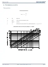
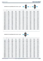
Page 45: ...ICAL DATA Pressure loss Pressure loss calculation Determination of pressure loss by using diagram 1 2 kg m3 p w2 2 p Pa presure loss w m s air flow speed in nominal damper section kg m3 air density co...

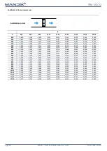
Page 46: ...501 0 484 0 473 0 466 0 460 0 456 0 452 600 0 592 0 528 0 499 0 482 0 471 0 464 0 458 0 454 0 450 650 0 590 0 526 0 497 0 480 0 469 0 462 0 456 0 452 0 448 700 0 588 0 524 0 495 0 478 0 468 0 460 0 4...

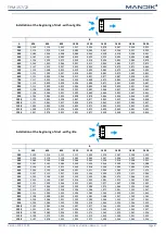
Page 47: ...60 0 850 0 842 0 836 1150 1 098 0 979 0 924 0 893 0 873 0 859 0 849 0 841 0 835 1200 1 097 0 978 0 923 0 893 0 872 0 858 0 848 0 840 0 834 Installation at the beginning of duct with grille B A 430 630...

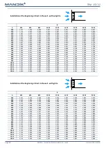
Page 48: ...93 0 783 0 776 0 770 1150 1 011 0 901 0 851 0 823 0 805 0 792 0 782 0 775 0 769 1200 1 010 0 900 0 851 0 822 0 804 0 791 0 781 0 774 0 768 Installation at the beginning of duct in the wall with grille...

Page 49: ...3 069 3 050 3 036 1150 3 642 3 366 3 241 3 169 3 123 3 090 3 066 3 048 3 033 1200 3 640 3 364 3 239 3 167 3 121 3 088 3 064 3 046 3 031 Installation in the wall between the rooms 2 grille B A 430 630...

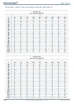
Page 50: ...7 38 38 1000 33 34 35 36 37 37 38 38 39 1050 33 34 35 36 37 37 38 38 39 1100 34 35 36 36 37 38 38 39 39 1150 34 35 36 36 37 38 38 39 39 1200 34 35 36 37 37 38 38 39 39 Air velocity 3 m s Level of acou...

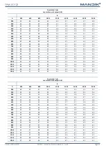
Page 51: ...54 54 54 1050 49 50 51 52 53 53 54 54 55 1100 49 50 51 52 53 53 54 54 55 1150 49 51 52 52 53 54 54 55 55 1200 50 51 52 53 53 54 54 55 55 Air velocity 5 m s Level of acoustic output dB B A 430 630 830...

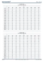
Page 52: ...65 66 66 1050 61 62 63 64 64 65 66 66 67 1100 61 62 63 64 65 65 66 66 67 1150 61 62 63 64 65 65 66 66 67 1200 61 62 63 64 65 66 66 67 67 Air velocity 8 m s Level of acoustic output dB B A 430 630 830...

Page 53: ...78 79 79 1050 73 75 76 77 77 78 79 79 79 1100 73 75 76 77 78 78 79 79 80 1150 74 75 76 77 78 78 79 79 80 1200 74 75 76 77 78 79 79 80 80 Air velocity 12 m s Level of acoustic output dB B A 430 630 83...

Page 54: ...holders including pins metal parts of blade Inspection hole cover and fasteners if they are parts of the cover Everything that is located or enters the inner space or the cross section of the damper i...

Page 55: ...al price of damper For unloading and further manipulation with the damper is necessary to use appropriate tooling forklifts due to damper weight Dampers are fragile Dampers are transported by box frei...

Page 56: ...silicate plates Procedure Use drill drill size acc To suit connecting cable 2 mm for seal up by mastic and make two holes It is possible to drill holes in any side of the housing Pull the heat resist...

Page 57: ...rill size acc to suit connecting cable 2 mm for seal up by mastic and make holes min pitch of the holes must be 30 mm number of holes depends on the type of control module It is possible to drill hole...

Page 58: ...ther appropriate way Results of regular checks imperfections found and all important facts connected with the damper function must be recorded in the FIRE BOOK and immediately repor ted to the operato...

Page 59: ...EN BEE BE for 24V 54 with actuating mechanism BEN BEE SR for 24V 65 Design 65 is not available by using actuating mechanism BE The surface of the grille is provided with powder coating standard colour...

Page 60: ...ual product information see www mandik co uk MAND K a s Dob sk 550 267 24 Hostomice Czech Republic Tel 420 311 706 742 E Mail mandik mandik cz Manufacturer MANDIK UK Ltd 130 Aztec West Bristol BS32 4U...

Reviews: