background image

www.malags.com 

36 


10   Upgrade 

__________________________________________________ 


The instructions below describe how to upgrade the application software of 
the CX.  


1. 

Download  the  file:  “ECX_080021.zip”.  The  file  must  be  unzipped 
once and then a file named “ram10img.gz” is seen, which is zipped 
as well, but should remain so. 

2. 

Copy the file “ram10img.gz” to a USB flash memory. 

3.  Connect the unit to a fully charged 12V power source and start it up. 

Note!


It’s  important  that  the  battery  is  fully  charged  to  avoid  power 

loss  during  the  upgrade  that  can  cause  damage  of  the  internal 
memory. 

4. 

Select  the  “Quit”  button  on  the  main  menu  and  go  to  the  system 
menu by turning the turn-push key 3 turns clockwise, 3 turns counter 
clockwise  and  3  turns  clockwise  again.  A  more  detailed  description 
on this can be found in the section on system settings. 

5.  Insert the USB memory device in the USB slot of the CX.  
6. 

Select  the  option  “Software  upgrade”  in  the  system  menu.  The 
upgrade starts and can take up to several minutes.  

7.  When  the  upgrade  is  done,  a  message  is  shown  that  the  upgrade 

was  successful.  Then  press  the  turn-push  key  once  and  CX  will  be 
rebooted 

8.  Remove the USB memory from the monitor and close the rubber cap 

onto the USB connector. 

 
Note! 

Use  a  proper  USB  Flash  Disk  or  USB  Flash  Reader  that  is  Linux 
compatible. This  is often  described  as: Operation  System Compatibility: .., 
Linux, 

…. or Compatible: Linux (kernel 2.6.0 or higher) 

 
Usually  when buying a USB Flash device, it is formatted as FAT16, which 
is suitable. 

.

Summary of Contents for CX

Page 1: ...MAL CX System Operating Manual v 2 3 EM 19 001024...

Page 2: ...CX Start up 5 3 2D Project 12 4 3D Project 14 4 1 Creating a 3D Project 15 4 2 Migration settings and Images for 3D Projects 19 5 Object Mapper Project 21 6 EM Option 23 6 1 Resulting signals images...

Page 3: ...equipment as well as your impressions of this manual Please take the time to read through the assembly instructions carefully and address any questions or suggestions to the following Main Office MAL...

Page 4: ...hipping thus permitting the instruments to move around inside the package 1 3 MAL Geoscience Indemnity Clause Operators of MAL CX or other MAL GPR systems shall hold harmless defend and indemnify MAL...

Page 5: ...l connections have been made the CX can be turned on Pressing the On Off button at top right hand corner activates the system More information on the High Frequency Antennas can be found in Chapter 12...

Page 6: ...in between the individual menus on the screen and activates the selection by pressing the two buttons at the same time The following screen is shown at start up of the CX and the work flow of the 3 d...

Page 7: ...rojects All these project types are explained in detail in the following chapters However for all of these three options general measurements settings are done first of all and in quite a similar way...

Page 8: ...w right side of the screen shows directly how the signal looks like Moving the antenna over a surface will change this view of the wiggle trace and the gray scale background Using the turn push button...

Page 9: ...s chosen accordingly to the medium the GPR investigation is carried out in The CX system lists a number of different types of material and is a guide for the operator when estimating the depth to targ...

Page 10: ...ption to carry out a short measurement find an object and by that a hyperbola to migrate or use for hyperbola fitting as tools to estimate the velocity Press Start to start the measurement Using the M...

Page 11: ...the wheel acquisition mode is available Point interval is fixed in 3D projects depending on the used antenna For all project types 2D 3D and Object Mapper the filename is given automatically by the CX...

Page 12: ...ow This type of project can for instance be used to the investigate layer thicknesses as concrete floors asphalt thicknesses on roads ice thickness etc When the measurement settings in the General Set...

Page 13: ...further interpretation work see the Section Transferring data Files can be continued by pressing NewP New Profile To start a new 2D project press Exit and then start from the main menu again To impro...

Page 14: ...he 3D Project option in the CX will guide you through all steps involved in the data collection to the final processed 2 5D view of the investigated area The measurement can be carried out using a gri...

Page 15: ...ect When the option 3D Project is chose and the measurements settings are made Note Point interval is fixed in 3D projects depending on the used antenna press to reach the 3D Project window The CX sys...

Page 16: ...or on the extension handle are used as remote controls for choosing the Next profile and Start profile The number in the blue rectangle refers to the distance on the grid carpet Place the antenna care...

Page 17: ...the CX system automatically will change to the second direction Once the last profile is filled press the red button one more time then press the Process button to process and view the data This will...

Page 18: ...everal targets on different depths in the same top view When the parameter is altered the time depth span is shown interactively on the side view Threshold This is a composed filter It mainly sets a t...

Page 19: ...ploaded to a computer see the section on Transferring Data 4 2 Migration settings and Images for 3D Projects When the 3D project is ready there are a number of different options available on the scree...

Page 20: ...image especially when seen in the top view Using this option an appropriate velocity for the migration can be selected by changing The is also a background removal filter for 3D project With the Image...

Page 21: ...Applications can be for instance mapping pipes conduits or other larger linear structures over larger areas Once an Object Mapper Project is created within the MAL CX it can be directly opened in Obje...

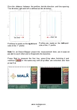
Page 22: ...hand side of the 1 st profile Profiles are made on the left hand side of the 1 st profile Note In an Object Mapper project the measurement lines are measured parallel to each other and orthogonal to t...

Page 23: ...ologies to better locate and identify energized power cables rebar post tension cables plus metallic and non metallic conduits in concrete slabs either suspended or on grade When an antenna with the E...

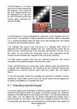
Page 24: ...coils in the antenna The EM sensor system built into the antenna measures the vertical amplitude of the leaked magnetic field from the cable There are EM sensors on each side of the antenna and they d...

Page 25: ...wisted cable the image might become blurred 6 2 Sensitivity The EM sensor system was designed with a detection limit equal to the leakage from a cable carrying 260mA at 10cm distance e g 60W in a 230V...

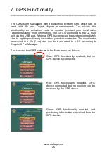
Page 26: ...main unit via the USB port When a GPS is connected the system immediately start to log the positioning data with x y and z coordinates The coordinates are saved in a file cor and can be transferred to...

Page 27: ...expressed in Greenwich Time zone An excerpt from a data file is seen below Trace date time latitude N longitude E height above MSL M HDOP 1 2008 05 14 08 52 44 59 368000 N 18 248722 E 15 9 M 2 4 2 200...

Page 28: ...3D Project called 1 File extension follows the above mentioned however EM data files are named 3D_001_1 emm or _2 Deleting moving a 3D project removes all files belonging to the project 3D_001_S0001 a...

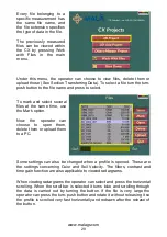
Page 29: ...use the Mark option Now the operator can choose to open them delete them or upload them to a PC Some settings can also be changed when a profile is opened These are the settings concerning Color and...

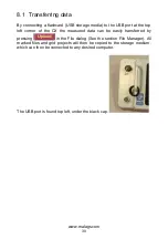
Page 30: ...op left corner of the CX the measured data can be easily transferred by pressing in the File dialog See the section File Manager All marked files and grid projects will then be copied to the storage m...

Page 31: ...r of stack can be chosen between 1 and 512 Changed under the option Stacks Screen shots data format Remote control on or off Activated if the system is used wit a remot control Power Save If the Power...

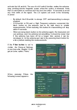
Page 32: ...screen is reached By activating the kill switch mandatory under certain conditions due to FCC regulations see FCC Part 15 509 stating that when working with the high frequency antenna as a hand held a...

Page 33: ...y antenna connected the black button on the antenna has to be held down to enable measurements When realizing this button the transmitting will stop within 9 seconds When pressing black button on the...

Page 34: ...noise from the signal the default parameters 25 and 5 will be appropriate Observe that the setting of the option BKG Removal only affects the FIR filter and works on a trace level as a high pass filt...

Page 35: ...vel is set to 11 V Meters are chosen as the measurement units By pressing Restore Factory Settings the system file in the CX is restored from the system file default image This is useful if the system...

Page 36: ...by turning the turn push key 3 turns clockwise 3 turns counter clockwise and 3 turns clockwise again A more detailed description on this can be found in the section on system settings 5 Insert the USB...

Page 37: ...onnect the battery before charging The battery charger is an automatic quick charger designed for Li Ion batteries The recharge up to about 80 of the full capacity goes very quickly However it is reco...

Page 38: ...alt mapping ice thickness etc See also Table 12 1 Table 12 1 Approximate depth ranges for different antenna frequencies Antenna frequency GHz Approximate Radial Resolution c 100 m s c 4 cm Approximate...

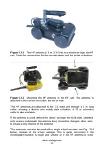
Page 39: ...ain unit through a 4 m long cable allowing a flexible and mobile data collection A 10 m extension cable is also available If the antenna is used without the wheel carriage the skid plate attached with...

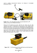
Page 40: ...uttons on the handle of the antenna Fig 12 5 or on the HF cart or extension pole By pressing either the black or red button the operator moves in between the individual menus on the screen and activat...

Page 41: ...g the data collection and the other one red on the handle top starting a new profile The extension handle with the control buttons is mounted on the wheel carriage or on the antenna itself and the ext...

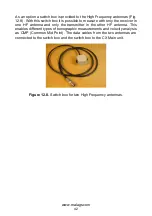
Page 42: ...ly the receiver in one HF antenna and only the transmitter in the other HF antenna This enables different types of tomographic measurements and velocity analysis as CMP Common Mid Point The data cable...

Page 43: ...y AC DC agg Input 100 240 AC Output 13 2 V DC 4 5 A Operating time 6 hours Charger Quick charger automatic charge cycle 100 240 V AC input Charge time 3 5 h 80 100 Input device Combined turn push butt...

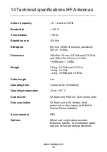
Page 44: ...and 190x115x110 mm 1 2 GHz 1 6 EM and 1 2 EM Weight 0 6 kg 1 6 GHz and 2 3 GHz 1 0 kg 1 2 GHz 1 2 kg 1 6 EM and 1 2 EM Cable length 4 m Operating time 3 hours with 12V battery Operating temperature 2...

Page 45: ...Fax 1 843 769 7392 E mail sales usa malags com MAL Geoscience China Room 2604 Yuan Chen Xin BLDG No 12 Yu Min Road Chao Yang District Beijing 100029 Phone 86 108 225 0728 Fax 86 108 225 0815 E mail sa...

Reviews: