background image

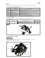
[3] DISASSEMBLY/ASSEMBLY

[3]-4. Bearing box, Helical gear 38 (cont.)

DISASSEMBLING

ASSEMBLING

Fig. 17

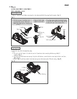
1. Remove Thickness ring before setting 

    Bearing box to vise.

3. Spindle can be used as a jig for removing

    Ball bearing 6102ZZ.

1R340

Thickness ring

Bearing box

Bearing 

retainer 19-33

2. Fix the Bearing box in Vise and 

    apply 1R340 to Bearing retainer

    19-33 as illustrated right.  

    Remove Bearing retainer 19-33

    by turning 1R340 clockwise. 
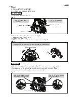
Ball bearing 

6201ZZ

4) Remove Ball Bearing 6201ZZ from Bearing box. (

Fig. 17

)

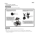
Assemble Bearing box section by doing the reverse of the disassembling steps,

Note:


1) Do not forget to set Thickness ring and mount Ring 12 after assembling Bearing box. (

right

 in 

Fig. 16

)

2) Be sure to use 

new

 Ball bearing 6201ZZ because


removed one was


damaged in the removal process of Spindle,

     Helical gear 38 and Ring 12.


Note: 

Do not reuse Ball bearing 6201ZZ

           removed from bearing box because it is


damaged in the removal process of 

           Spindle, Helical gear 38 and Ring 12.


9

/


1

0

R

epair

Summary of Contents for MT582

Page 1: ...rability at less expense In compliance with the regulations of the EC directives Ergonomically designed soft grip covered with non slip elastomer Guide rule 1 pc Hex wrench 5 1 pc Dust nozzle 1 pc for European countries only TCT saw blade 1 pc Dimensions mm Width W Height H Length L 297 11 3 4 232 9 1 8 255 10 L W H Diameter mm Hole diameter mm Size of blade No load speed min 1 rpm Max cutting cap...

Page 2: ...earing from Armature Removing Helical gear 38 Removing Mounting Retaining ring S 12 Removing Assembling Bearing retainer 19 33 Item No Apply Makita Grease N No 1 to the pointed area with triangles to protect parts and product from unusual abrasion Description Helical gear 38 20 Blade case complete a a Gear room where Helical gear 38 rotates b b O Ring 26 built in the Armature insertion hole a litt...

Page 3: ...ove M8x24 Flat head square neck bolt M6x20 Pan head screw M8 13 Hex nut Flat washer 8 M8x24 Flat head square neck bolt Lever plate Lever plate Bow stop ring E 12 3 Unscrew M8 13 Hex nut by using Lever plate as a Wrench and remove Flat washer 8 M8x24 Flat head square neck bolt cannot be removed yet in this step as its bolt head side is blocked by Safety cover 2 Remove Bow stop ring E 12 by twisting...

Page 4: ...Fig 5 6 Loosen M5 Pan head screw while blocking M5 Hex nut with Wrench 8 7 Remove M5 Pan head screw M5 Hex nut and Spring washer 5 8 Base can be wholly separated from Blade case complete Fig 5 Angular plate M5 Hex nut Base M5 Hex nut Wrench 8 Spring washer 5 M5 Pan head screw M5 Pan head screw P 4 10 Repair ...

Page 5: ...ver plate Fig 6 6 Fix Lever plate with Bow stop ring E 12 Fig 7 ASSEMBLING DISASSEMBLING within 30 degrees Lever plate Assemble Bow stop ring E 12 to Lever plate Note The concave side of the ring must face Lever plate as drawn below so that Lever plate can be securely fastened with M8 13 Hex nut Lever plate must be fixed in place so that it can be locked at an angle between 0 and 30 degrees as dra...

Page 6: ...ade case complete before inserting Armature into there left in Fig 9 c Insert O ring 18 and Flat washer 14 into the bearing box at bottom inside of Motor housing Fig 10 Armature Ball bearing 6000ZZ Ball bearing 608ZZ 3 Pull out Armature from Blade case complete then remove Shaft lock Note Be careful not lose Compression spring 5 4 Remove Ball bearing 6000ZZ with 1R269 Shaft lock Compression spring...

Page 7: ...ntle Base Figs 3 4 5 4 Blade case complete can be replaced after removing Bearing box Fig 12 1 Assemble Bearing box to Blade case complete Fig 12 2 Assemble Base to Blade case complete by doing the reverse of the steps described in Figs 5 4 3 3 Assemble Armature and Motor housing by doing the reverse of the steps described in Figs 9 8 4 Assemble Safety cover to Bearing box section as instructed in...

Page 8: ... 12 with 1R291 3 Put Bearing box on 1R217 then applying 1R032 to the stepped portion of Spindle as illustrated below strike the 1R032 with Arbor press carefully and push out Spindle halfway as illustrated below 1R032 Bearing Box 1R217 1R280 4 Apply 1R280 and press it with Arbor press until Spindle Helical gear 38 and Ring 12 are removed from Bearing box Spindle Arbor Press Bearing box Retaining ri...

Page 9: ...er 19 33 by turning 1R340 clockwise Ball bearing 6201ZZ 4 Remove Ball Bearing 6201ZZ from Bearing box Fig 17 Assemble Bearing box section by doing the reverse of the disassembling steps Note 1 Do not forget to set Thickness ring and mount Ring 12 after assembling Bearing box right in Fig 16 2 Be sure to use new Ball bearing 6201ZZ because removed one was damaged in the removal process of Spindle H...

Page 10: ... Field lead wires 2 x black in these Lead wire holders Fix Field lead wires 2 x black in these Lead wire holders Field Fig D 1 Fig D 2 Power supply cord This Lead wire is brown for some countries This Lead wire is blue for some countries Pull Field lead wires 2 x black toward Strain relief side in order to tighten them in Motor housing Then put the consequent slack into this space Field lead wire ...

Reviews: