C
ircuit diagram
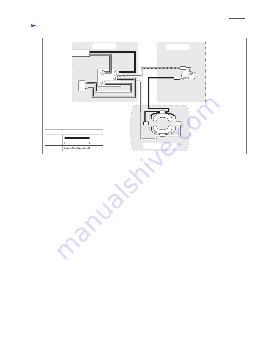
P 9 /10
BlackWhiteOrange
Color index of lead wires' sheath
Brake switch
Front Grip Side
Rear Grip Side
Main Switch
Power SupplyCord
Field
Noisesuppressor
Rear Grip
Motor Housing
Front Grip
Fig. 19
Page 1: ...pe 90SG 52E 90SG 56E 90SG 46E Chain blade 1 pc UC3020A 90SG 46E UC3520A 90SG 52E UC4020A 90SG 56E Guide bar 1 pc UC3020A 90SG 12 UC3520A 90SG 14 UC4020A 90SG 16 Ghain cover 1 pc Hook complete 1 pc The...
Page 2: ...ng L by removing nine 4x18 Tapping screws Note Housing R can be separated without removing Sprocket Important Do not remove Oil tank cap in this step 2 The parts marked with and can now be replaced Fi...
Page 3: ...that the tabs of Clamp is positioned on the Housing R installation side as illustrated in Fig 5 Then connect the other end of Oil tube securely to Oil pump complete 4 Assemble the lubricating mechani...
Page 4: ...ating mechanism Fig 3 on page 3 and check whether the following parts are clogged with foreign matter Filter in Oil tank Oil tube Oil pump complete If clogged remove foreign matter and clean up the pa...
Page 5: ...ure and Armature starts rotating 1 When Front hand guard is pushed towards Chain bar Link plate complete is bent by the projection on the guard 2 Brake band is pulled by the bent Link plate complete T...
Page 6: ...Tapping screws Fig 9 4 Put the machine as illustrated in Fig 10 Remove Rear cover then Carbon brush The assembly of Armature and Bearing holder can now be removed 5 By hooking Rod on the notch of Bea...
Page 7: ...liers in the direction of the gray arrow with adjustable pliers Fig 14 9 By removing Pin 5 Link plate complete and Compression spring 9 can be separated from Bearing holder Fig 15 Link plate complete...
Page 8: ...locked when Switch lever is pulled for starting operation Fig 18 Compression spring 9 of link plate complete has to be set in the rib of bearing holder exactly Fig 15 on page 7 2 Unlock Kick back brak...
Page 9: ...t diagram P 9 10 Black White Orange Color index of lead wires sheath Brake switch Front Grip Side Rear Grip Side Main Switch Power SupplyCord Field Noise suppressor Rear Grip Motor Housing Front Grip...
Page 10: ...tch The recectaples have to face the wall of housing set L A Field Lead Wire black to Brake Switch Route it between rib A and rib B B Field Lead Wire white to main switch Route it between rib C and ri...