background image

the tool manufacturer.

 Just because the 

accessory can be attached to your power tool, it 
does not assure safe operation. 

4. 

The rated speed of the accessory must be at 
least equal to the maximum speed marked on 
the power tool.

 Accessories running faster than 

their rated speed can break and fly apart. 

5. 

The outside diameter and the thickness of your 
accessory must be within the capacity rating of 
your power tool.

 Incorrectly sized accessories 

cannot be adequately guarded or controlled. 

6. 

The arbour size of wheels, flanges, backing 
pads or any other accessory must properly fit 
the spindle of the power tool.

 Accessories with 

arbour holes that do not match the mounting 
hardware of the power tool will run out of balance, 
vibrate excessively and may cause loss of control. 

7. 

Do not use a damaged accessory. Before each 
use inspect the accessory such as abrasive 
wheels for chips and cracks, backing pad for 
cracks, tear or excess wear, wire brush for 
loose or cracked wires. If power tool or 
accessory is dropped, inspect for damage or 
install an undamaged accessory. After 
inspecting and installing an accessory, 
position yourself and bystanders away from 
the plane of the rotating accessory and run the 
power tool at maximum no-load speed for one 
minute.

 Damaged accessories will normally break 

apart during this test time. 

8. 

Wear personal protective equipment. 
Depending on application, use face shield, 
safety goggles or safety glasses. As 
appropriate, wear dust mask, hearing 
protectors, gloves and workshop apron 
capable of stopping small abrasive or 
workpiece fragments.

 The eye protection must 

be capable of stopping flying debris generated by 
various operations . The dust mask or respirator 
must be capable of filtrating particles generated by 
your operation. Prolonged exposure to high 
intensity noise may cause hearing loss. 

9. 

Keep bystanders a safe distance away from 
work area. Anyone entering the work area 
must wear personal protective equipment.


Fragments of workpiece or of a broken accessory 
may fly away and cause injury beyond immediate 
area of operation. 

10. 

Hold the power tool by insulated gripping 
surfaces only, when performing an operation 
where the cutting accessory may contact 
hidden wiring or its own cord.

 Cutting 

accessory contacting a "live" wire may make 
exposed metal parts of the power tool "live" and 
could give the operator an electric shock. 

11. 

Position the cord clear of the spinning 
accessory.

 If you lose control, the cord may be cut 

or snagged and your hand or arm may be pulled 
into the spinning accessory.   

12. 

Never lay the power tool down until the 
accessory has come to a complete stop.

 The 

spinning accessory may grab the surface and pull 
the power tool out of your control. 

13. 

Do not run the power tool while carrying it at 
your side.

 Accidental contact with the spinning 

accessory could snag your clothing, pulling the 
accessory into your body.   

14. 

Regularly clean the power tool’s air vents.

 The 

motor’s fan will draw the dust inside the housing 
and excessive accumulation of powdered metal 
may cause electrical hazards. 

15. 

Do not operate the power tool near flammable 
materials.

 Sparks could ignite these materials. 

16. 

Do not use accessories that require liquid 
coolants.

 Using water or other liquid coolants may 

result in electrocution or shock. 

Kickback and Related Warnings


Kickback is a sudden reaction to a pinched or snagged 
rotating wheel, backing pad, brush or any other accessory. 
Pinching or snagging causes rapid stalling of the rotating 
accessory which in turn causes the uncontrolled power 
tool to be forced in the direction opposite of the 
accessory’s rotation at the point of the binding. 
For example, if an abrasive wheel is snagged or pinched 
by the workpiece, the edge of the wheel that is entering 
into the pinch point can dig into the surface of the 
material causing the wheel to climb out or kick out. The 
wheel may either jump toward or away from the operator, 
depending on direction of the wheel’s movement at the 
point of pinching. Abrasive wheels may also break under 
these conditions. 
Kickback is the result of power tool misuse and/or 
incorrect operating procedures or conditions and can be 
avoided by taking proper precautions as given below. 

a) 

Maintain a firm grip on the power tool and 

position your body and arm to allow you to 
resist kickback forces. Always use auxiliary 
handle, if provided, for maximum control over 
kickback or torque reaction during start-up.


The operator can control torque reactions or 
kickback forces, if proper precautions are taken. 
b) 

Never place your hand near the rotating 

accessory.

 Accessory may kickback over your 

hand. 
c) 

Do not position your body in the area where 

power tool will move if kickback occurs.


Kickback will propel the tool in direction opposite to 
the wheel’s movement at the point of snagging. 
d) 

Use special care when working corners, 

sharp edges etc. Avoid bouncing and snagging 

Summary of Contents for SA4540C

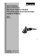
Page 1: ...D INSTRUCTION MANUAL DE INSTRUCCIONES DOUBLE INSULATION DOUBLE ISOLATION DOBLE AISLAMIENTO IMPORTANT Read Before Using IMPORTANT Lire avant usage IMPORTANTE Leer antes de usar Angle Sander Ponceuse Pulidora Angular SA4540C 012905 ...

Page 2: ...ool will increase the risk of electric shock 7 Do not abuse the cord Never use the cord for carrying pulling or unplugging the power tool Keep cord away from heat oil sharp edges or moving parts Damaged or entangled cords increase the risk of electric shock 8 When operating a power tool outdoors use an extension cord suitable for outdoor use Use of a cord suitable for outdoor use reduces the risk ...

Page 3: ...of the power tool for operations different from those intended could result in a hazardous situation Service 24 Have your power tool serviced by a qualified repair person using only identical replacement parts This will ensure that the safety of the power tool is maintained 25 Follow instruction for lubricating and changing accessories 26 Keep handles dry clean and free from oil and grease USE PRO...

Page 4: ... operator an electric shock 11 Position the cord clear of the spinning accessory If you lose control the cord may be cut or snagged and your hand or arm may be pulled into the spinning accessory 12 Never lay the power tool down until the accessory has come to a complete stop The spinning accessory may grab the surface and pull the power tool out of your control 13 Do not run the power tool while c...

Page 5: ... Never attempt to remove the cut off wheel from the cut while the wheel is in motion otherwise kickback may occur Investigate and take corrective action to eliminate the cause of wheel binding d Do not restart the cutting operation in the workpiece Let the wheel reach full speed and carefully re enter the cut The wheel may bind walk up or kickback if the power tool is restarted in the workpiece e ...

Page 6: ...fter the tool is switched off 33 If working place is extremely hot and humid or badly polluted by conductive dust use a short circuit breaker 30 mA to assure operator safety 34 Do not use the tool on any materials containing asbestos 35 Do not use water or grinding lubricant 36 Ensure that ventilation openings are kept clear when working in dusty conditions If it should become necessary to clear d...

Page 7: ...dication lamp lights up green when the tool is plugged If the indication lamp does not light up the mains cord or the controller may be defective The indication lamp is lit but the tool does not start even if the tool is switched on the carbon brushes may be worn out or the controller the motor or the ON OFF switch may be defective Unintentional restart proof The tool does not start with the switc...

Page 8: ...ol will operate as normal ASSEMBLY CAUTION Always be sure that the tool is switched off and unplugged before carrying out any work on the tool Installing side grip handle 1 012908 012911 CAUTION Always be sure that the side grip is installed securely before operation Remove one of the screws which secure the head cover Then screw the side grip into the screw hole Installing pad and abrasive disc 1...

Page 9: ...eel guard follow the installation procedure in reverse For tool with clamp lever type wheel guard 1 2 3 4 009430 Pull the lever in the direction of the arrow after loosening the screw Mount the wheel guard with the protrusions on the wheel guard band aligned with the notches on the bearing box Then rotate the wheel guard around 180 ゚ 1 2 009431 Tighten the wheel guard with fastening the screw afte...

Page 10: ...ttachment so that the marking A B C or D places as shown Snap its pins in the vents Dust cover attachment can be removed by hand NOTE Clean out the dust cover attachment when it is clogged with dust or foreign matters Continuing operation with a clogged dust cover attachment will damage the tool OPERATION WARNING It should never be necessary to force the tool The weight of the tool applies adequat...

Page 11: ...signed for use with cut off wheels NEVER use cut off wheel for side grinding Do not jam the wheel or apply excessive pressure Do not attempt to make an excessive depth of cut Overstressing the wheel increases the loading and susceptibility to twisting or binding of the wheel in the cut and the possibility of kickback wheel breakage and overheating of the motor may occur Do not start the cutting op...

Page 12: ...on or maintenance Never use gasoline benzine thinner alcohol or the like Discoloration deformation or cracks may result 1 2 012732 The tool and its air vents have to be kept clean Regularly clean the tool s air vents or whenever the vents start to become obstructed To maintain product SAFETY and RELIABILITY repairs carbon brush inspection and replacement any other maintenance or adjustment should ...

Page 13: ...d center wheel Multi disc Lock nut 5 8 45 Abrasive disc Wire wheel brush Rubber pad 100 Rubber pad 115 Sanding lock nut 5 8 48 Wire cup brush Lock nut wrench 28 Abrasive cut off wheel Diamond wheel Wheel Guard for cut off wheel 012986 NOTE Some items in the list may be included in the tool package as standard accessories They may differ from country to country ...

Page 14: ...GES FROM THE SALE OR USE OF THE PRODUCT THIS DISCLAIMER APPLIES BOTH DURING AND AFTER THE TERM OF THIS WARRANTY MAKITA DISCLAIMS LIABILITY FOR ANY IMPLIED WARRANTIES INCLUDING IMPLIED WARRANTIES OF MERCHANTABILITY AND FITNESS FOR A SPECIFIC PURPOSE AFTER THE ONE YEAR TERM OF THIS WARRANTY This Warranty gives you specific legal rights and you may also have other rights which vary from state to stat...

Page 15: ...urant Ne modifiez jamais la fiche de quelque façon que ce soit N utilisez aucun adaptateur de fiche sur les outils électriques avec mise à la terre En ne modifiant pas les fiches et en les insérant dans des prises de courant pour lesquelles elles ont été conçues vous réduirez les risques de choc électrique 5 Évitez tout contact corporel avec les surfaces mises à la terre telles que les tuyaux radi...

Page 16: ...e ou de ranger l outil électrique De telles mesures préventives réduisent les risques de démarrage accidentel de l outil électrique 20 Après l utilisation d un outil électrique rangez le hors de portée des enfants et ne laissez aucune personne l utiliser si elle n est pas familiarisée avec l outil électrique ou les présentes instructions d utilisation Les outils électriques représentent un danger ...

Page 17: ...rotéger ou de contrôler adéquatement les accessoires d une dimension inappropriée 6 La dimension de l alésage des meules des flasques des plaques de presse ou de tout autre accessoire doit s ajuster correctement à l axe de l outil Les accessoires dotés d alésages centraux ne correspondant pas à la fixation de l outil fonctionneront en déséquilibre ils vibreront de manière excessive et cela pourrai...

Page 18: ...aire détacher la meule La meule peut s éjecter en direction de l opérateur ou au loin selon la direction du mouvement de la meule au point de pincement Les meules abrasives peuvent aussi se casser dans de telles conditions Le recul est le résultat d une utilisation inadéquate de l outil électrique et ou de procédures ou conditions d utilisation incorrectes on peut l éviter en prenant des précautio...

Page 19: ...ement prudent lorsque vous découpez une ouverture dans une cloison existante ou tout autre matériau dont l arrière n est pas visible La meule pourrait couper une conduite de gaz ou d eau des fils électriques ou des objets ce qui provoquerait un recul Mises en garde de sécurité particulières pour le ponçage a N utilisez pas de disque abrasif surdimensionné Respectez les recommandations du fabricant...

Page 20: ... court circuit 30 mA afin d assurer que l opérateur est protégé adéquatement 34 N utilisez pas l outil sur des matériaux contenant de l amiante 35 N utilisez pas d eau ou de lubrifiant à meulage 36 Assurez vous que les fentes d aération sont dégagées lorsque vous fonctionnez dans des conditions poussiéreuses S il devient nécessaire de nettoyer la poussière commencez par déconnecter l alimentation ...

Page 21: ...glissière puis faites le glisser sur la position O OFF Voyant lumineux 1 012729 Le voyant lumineux s allume en vert si l outil est branché Si le voyant ne s allume pas le cordon ou le contrôleur peut être défectueux Si le voyant lumineux est allumé et que l interrupteur est en position marche mais que l outil ne démarre pas il se peut que les peut que les charbons soient usés ou que le contrôleur ...

Page 22: ... charge revient à des niveaux admissibles l outil fonctionnera normalement ASSEMBLAGE ATTENTION Avant d effectuer toute intervention sur l outil assurez vous toujours qu il est hors tension et débranché Installation de la poignée latérale poignée 1 012908 012911 ATTENTION Avant d utiliser l outil assurez vous toujours que la poignée latérale est installée de façon sûre Retirez l une des vis qui fi...

Page 23: ...aites ensuite tourner le carter de meule de 180 ゚ dans le sens inverse des aiguilles d une montre Assurez vous d avoir serré la vis fermement Pour retirer le carter de meule suivez la procédure de l installation de l autre côté Pour outil avec carter de meule à levier de serrage 1 2 3 4 009430 Après avoir desserré la vis tirez le levier dans la direction indiquée par la flèche Montez le carter de ...

Page 24: ...ser La fixation du pare poussière est composée de quatre pièces chacune étant utilisée dans une position différente 1 2 3 4 012731 Positionnez la fixation du pare poussière pour que le repère A B C ou D soit placé comme indiqué Insérez ses broches dans les orifices d aération La fixation du pare poussière peut être retirée manuellement NOTE Nettoyez la fixation du pare poussière lorsque de la pous...

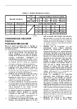
Page 25: ... Épaisseur 4 mm 5 32 po ou plus Épaisseur Moins de 4 mm 5 32 po Épaisseur 4 mm 5 32 po ou plus 22 23 mm 7 8 22 23 mm 7 8 22 23 mm 7 8 1 2 3 1 4 3 Meule diamantée 4 Bague interne 3 Meule à découper 2 Contre écrou 1 011644 AVERTISSEMENT Lorsque vous utilisez une meule abrasive à tronçonner roue diamantée assurez vous d utiliser seulement les carters de meule conçus spécialement pour ces meules à déc...

Page 26: ...rter en vous assurant que le diamètre de la brosse n est pas trop grand pour le carter La brosse peut se casser en cours d utilisation et le carter réduit alors les risques de blessure 1 012744 Débranchez l outil et placez le la tête en bas pour permettre un accès facile à l arbre Retirez tous les accessoires de l arbre Enfilez la brosse métallique circulaire sur l arbre et serrez avec les clés Lo...

Page 27: ...vous blesser ou blesser autrui Si vous désirez obtenir plus de détails concernant ces accessoires veuillez contacter le centre de service après vente Makita le plus près Disque abrasif Fixation du pare poussière 5 9 4 7 8 1 3 5 3 12 2 2 10 6 11 1 2 3 4 5 6 7 8 9 10 11 12 Modèle 115 mm 4 1 2 po Modèle 125 mm 5 po Poignée 36 Carter de meule pour la roue de meulage Bague interne 45 Meule à moyeu dépo...

Page 28: ...IT CET AVIS DE NON RESPONSABILITÉ S APPLIQUE À LA FOIS PENDANT ET APRÈS LA PÉRIODE COUVERTE PAR CETTE GARANTIE MAKITA DÉCLINE TOUTE RESPONSABILITÉ QUANT À TOUTE GARANTIE TACITE INCLUANT LES GARANTIES TACITES DE QUALITÉ MARCHANDE ET ADÉQUATION À UN USAGE PARTICULIER APRÈS LA PÉRIODE D UN AN COUVERTE PAR CETTE GARANTIE Cette garantie vous donne des droits spécifiques reconnus par la loi et possiblem...

Page 29: ...den hacer perder el control Seguridad eléctrica 4 Las clavijas de conexión de las herramientas eléctricas deberán encajar perfectamente en la toma de corriente No modifique nunca la clavija de conexión de ninguna forma No utilice ninguna clavija adaptadora con herramientas eléctricas que tengan conexión a tierra puesta a tierra La utilización de clavijas no modificadas y que encajen perfectamente ...

Page 30: ...léctrica antes de realizar ajustes cambiar accesorios o guardar las herramientas eléctricas Dichas medidas de seguridad preventivas reducen el riesgo de que la herramienta se inicie accidentalmente 20 Guarde la herramienta eléctrica que no use fuera del alcance de los niños y no permita que las personas que no están familiarizadas con ella o con las instrucciones la operen Las herramientas eléctri...

Page 31: ...ueden desintegrarse 5 El diámetro externo y el grosor de su accesorio debe estar dentro de la capacidad indicada de su herramienta eléctrica Los accesorios de tamaño que no corresponda para usarse con la herramienta no podrán ser controlados o protegidos adecuadamente 6 El tamaño del eje de los discos así como las bridas y las almohadillas de soporte o cualquier otro accesorio deben encajar correc...

Page 32: ...nto Por ejemplo si un disco abrasivo se traba o atasca debido a la pieza de trabajo el borde del disco que está ingresando hacia el punto de atascamiento puede introducirse hacia la superficie del material ocasionando que el disco se salga bruscamente Puede que el disco salte hacia el operador o hacia dirección opuesta de él dependiendo de la dirección del movimiento del disco al momento del atasc...

Page 33: ...en el corte Puede que el disco se atasque se salga del camino o que genere un retroceso brusco si se reinicia estando insertado en la pieza de trabajo e Los tableros de soporte o las piezas de trabajo de tamaño muy grande minimizan el riesgo de que el disco se atasque o tenga un retroceso brusco Las piezas de trabajo grandes tienden a pandearse debido a su propio peso Deben colocarse soportes bajo...

Page 34: ...a longitud del eje 31 Verifique que la pieza de trabajo esté correctamente sostenida 32 Tenga cuidado puesto que el disco continúa girando después de apagada la herramienta 33 Si el lugar de trabajo es extremadamente caliente y húmedo o muy contaminado con polvo conductor utilice un interruptor de corto circuito de 30 mA para garantizar la seguridad del operario 34 No utilice la herramienta con ma...

Page 35: ...O OFF Luz indicadora 1 012729 La luz indicadora se ilumina en verde al conectar la herramienta Si la luz indicadora no se ilumina puede que haya un defecto con el cable eléctrico o el controlador Si la luz indicadora está iluminada pero la herramienta no se activa incluso al activar el interruptor de encendido ON puede que las escobillas de carbón estén desgastadas o bien que el controlador o el i...

Page 36: ...obrecalentamiento Cuando la carga de trabajo vuelve a un nivel aceptable la herramienta reanuda la operación normal ENSAMBLE PRECAUCIÓN Asegúrese siempre de que la herramienta esté apagada y desconectada antes de realizar cualquier trabajo en la misma Instalación de la empuñadura lateral mango 1 012908 012911 PRECAUCIÓN Antes de realizar una operación asegúrese siempre de que la empuñadura lateral...

Page 37: ...2 3 012733 Coloque el protector de disco con las protuberancias en la banda de este protector alineada con las ranuras de la caja de cojinetes Luego gire el protector de disco unos 180 ゚ en dirección contraria a las manecillas del reloj Asegúrese de ajustar bien el tornillo Para desmontar el protector de disco siga el procedimiento de instalación a la inversa Para herramienta con protector de disc...

Page 38: ...stalación a la inversa Instalación o desmontaje de la cubierta contra el polvo accesorio opcional ADVERTENCIA Asegúrese siempre de que la herramienta esté apagada y desenchufada antes de poner o quitar aditamento contra el polvo No seguir esta indicación puede causar daños a la herramienta así como lesiones a la persona Hay cuatro piezas para el aditamento de cubierta contra el polvo y cada una se...

Page 39: ...s piezas de metal Encienda la herramienta y después aplique el disco a la pieza de trabajo En general mantenga el borde de la rueda o disco a un ángulo de 15 ゚ aproximadamente con la superficie de la pieza de trabajo Durante el periodo de asentamiento de un disco nuevo no opere el esmeril en la dirección B o cortará en la pieza de trabajo Una vez que la orilla del disco se ha redondeado con el uso...

Page 40: ...la misma 1 012743 Desconecte la herramienta y póngala al revés para permitir un acceso fácil al eje Quite cualquier accesorio que haya en el eje Rosque la carda de alambres en el eje y apriétela con la llave suministrada Cuando utilice la carda evite aplicar presión excesiva que haga doblar demasiado los alambres ocasionando una rotura prematura Operación con una carda o disco de cepillo de alambr...

Page 41: ... acoplamientos conllevará un riesgo de sufrir heridas personales Utilice los accesorios o acoplamientos solamente para su fin establecido Su herramienta se suministra con un protector de disco de centro hundido multidisco disco flexible y disco de cepillo de alambre Un disco de corte también puede usarse con un protector opcional Si decide usar su amoladora Makita con los accesorios aprobados los ...

Page 42: ... 45 Disco de lija Carda o disco de cepillo de alambres Plato de goma 100 Plato de goma 115 Contratuerca de lijado 5 8 48 Cepillo de copa Llave de tuerca de bloqueo 28 Disco de corte abrasivo Disco de diamante Protector de disco Para disco de corte 012986 NOTA Algunos de los artículos en la lista puede que vengan junto con el paquete de la herramienta como accesorios incluidos Puede que estos acces...

Page 43: ...VENTA O USO DEL PRODUCTO ESTA RENUNCIA SERÁ APLICABLE TANTO DURANTE COMO DESPUÉS DEL TÉRMINO DE ESTA GARANTÍA MAKITA RENUNCIA LA RESPONSABILIDAD POR CUALQUIER GARANTÍA IMPLÍCITA INCLUYENDO GARANTÍAS IMPLÍCITAS DE COMERCIALIDAD E IDONEIDAD PARA UN FIN ESPECÍFICO DESPUÉS DEL TÉRMINO DE UN AÑO DE ESTA GARANTÍA Esta garantía le concede a usted derechos legales específicos y usted podrá tener también o...

Page 44: ... tipos de polvo creados por el lijado serrado amolado taladrado y otras actividades de la construccion contienen sustancias quimicas reconocidas por el Estado de California como causantes de cancer defectos de nacimiento y otros peligros de reproduccion Algunos ejemplos de estos productos quimicos son plomo de pinturas a base de plomo silice cristalino de ladrillos y cemento y otros productos de a...

Reviews: