background image

4

ENGLISH 

(Original instructions)

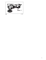
Explanation of general view 

1

Shaft lock

2

Cover

3

Slide switch

4

Speed adjusting dial

5

Lever

6

Close

7

Open

8

Abrasive disc

9

Pad

10 Spindle
11 Exhaust vent
12 Inhalation vent 

SPECIFICATION

• Due to our continuing program of research and devel-

opment, the specifications herein are subject to change
without notice. 

• Specifications may differ from country to country. 
• Weight according to EPTA-Procedure 01/2003

ENE057-1

Intended use

The tool is intended for surface work with natural stone.

ENF002-2

Power supply 

The tool should be connected only to a power supply of
the same voltage as indicated on the nameplate, and can
only be operated on single-phase AC supply. They are
double-insulated and can, therefore, also be used from
sockets without earth wire.

GEA010-1

General Power Tool Safety Warnings

WARNING Read all safety warnings and all

instructions. 

Failure to follow the warnings and

instructions may result in electric shock, fire and/or
serious injury.

Save all warnings and instructions for future reference.

GEB052-3

STONE POLISHER SAFETY WARNINGS

Safety Warnings Common for Polishing Operation:
1.

This power tool is intended to function as a pol-
isher. Read all safety warnings, instructions,
illustrations and specifications provided with
this power tool. 

Failure to follow all instructions

listed below may result in electric shock, fire and/or
serious injury.

2.

Operations such as grinding, sanding, wire
brushing or cutting-off are not recommended to
be performed with this power tool. 

Operations for

which the power tool was not designed may create a
hazard and cause personal injury.

3.

Do not use accessories which are not specifi-
cally designed and recommended by the tool
manufacturer. 

Just because the accessory can be

attached to your power tool, it does not assure safe
operation.

4.

The rated speed of the accessory must be at
least equal to the maximum speed marked on
the power tool. 

Accessories running faster than

their rated speed can break and fly apart.

5.

The outside diameter and the thickness of your
accessory must be within the capacity rating of
your power tool. 

Incorrectly sized accessories can-

not be adequately guarded or controlled.

6.

The arbour size of backing pads or any other
accessory must properly fit the spindle of the
power tool. 

Accessories with arbour holes that do

not match the mounting hardware of the power tool
will run out of balance, vibrate excessively and may
cause loss of control.

7.

Do not use a damaged accessory. Before each
use inspect the accessory such as backing pad
for cracks. If power tool or accessory is dropped,
inspect for damage or install an undamaged
accessory. After inspecting and installing an
accessory, position yourself and bystanders
away from the plane of the rotating accessory
and run the power tool at maximum no-load
speed for one minute. 

Damaged accessories will

normally break apart during this test time.

8.

Wear personal protective equipment. Depending
on application, use face shield, safety goggles
or safety glasses. As appropriate, wear dust
mask, hearing protectors, gloves and workshop
apron capable of stopping small abrasive or
workpiece fragments. 

The eye protection must be

capable of stopping flying debris generated by vari-
ous operations. The dust mask or respirator must be
capable of filtrating particles generated by your oper-
ation. Prolonged exposure to high intensity noise
may cause hearing loss.

9.

Keep bystanders a safe distance away from work
area. Anyone entering the work area must wear
personal protective equipment.

 Fragments of work-

piece or of a broken accessory may fly away and
cause injury beyond immediate area of operation.

10. Hold the power tool by insulated gripping sur-

faces only, when performing an operation where
the cutting accessory may contact hidden wiring
or its own cord.

 Cutting accessory contacting a

“live” wire may make exposed metal parts of the
power tool “live” and could give the operator an elec-
tric shock.

11. Position the cord clear of the spinning acces-

sory. 

If you lose control, the cord may be cut or

snagged and your hand or arm may be pulled into
the spinning accessory.

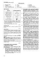
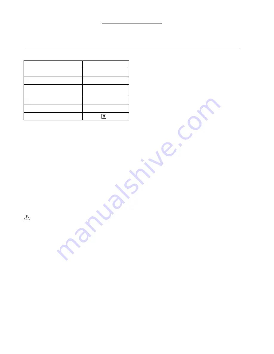
Model

PW5000C/PW5000CH

Spindle thread 

M14

Pad diameter

Max. 125 mm

Rated speed (n) / 

No load speed (n

0

)

2,000 – 4,400 min

–1

Overall length

313 mm

Net weight

2.3 kg

Safety class

/II

Summary of Contents for PW5000C

Page 1: ...inpolierer Betriebsanleitung I Lucidatrice ad umido Istruzioni per l uso NL Steen polijstmachine Gebruiksaanwijzing E Pulidora para piedra Manual de instrucciones P Polidora para pedra Manual de instruções DK Stenpudser Brugsanvisning GR Στιλβωτής λίθων Οδηγίες χρήσεως PW5000C PW5000CH ...

Page 2: ...2 1 2 3 4 5 6 7 8 8 9 10 5 A 7 6 B 3 1 2 4 004729 012116 004731 012117 004733 012118 012119 012120 ...

Page 3: ...3 9 11 12 012121 ...

Page 4: ...your accessory must be within the capacity rating of your power tool Incorrectly sized accessories can not be adequately guarded or controlled 6 The arbour size of backing pads or any other accessory must properly fit the spindle of the power tool Accessories with arbour holes that do not match the mounting hardware of the power tool will run out of balance vibrate excessively and may cause loss o...

Page 5: ...ions a Do not use excessively oversized abrasive disc Follow manufacturers recommendations when selecting abrasive disc Larger abrasive disc extending beyond the pad presents a laceration haz ard and may cause snagging tearing of the disc or kickback Additional Safety Warnings 16 Do not leave the tool running Operate the tool only when hand held 17 Always be sure that the tool is switched off and ...

Page 6: ...employed over the admissible load it will stop automatically to protect the motor and wheel When the load will come to the admissible level again the tool can be started automatically Opening or closing of water lever Fig 4 To keep the lever on the tool for water flow open turn it to the position A where the water passage will be ready Return it to the position B to close ASSEMBLY CAUTION Always b...

Page 7: ...lishing Vibration emission ah P 5 0 m s2 Uncertainty K 1 5 m s2 ENG902 1 The declared vibration emission value has been mea sured in accordance with the standard test method and may be used for comparing one tool with another The declared vibration emission value may also be used in a preliminary assessment of exposure The declared vibration emission value is used for main applications of the powe...

Page 8: ...outil Même s il est possible de fixer un accessoire à l outil électrique cela ne garantit pas qu il fonction nera de manière sûre 4 La vitesse nominale de l accessoire doit être au moins égale à la vitesse maximale indiquée sur l outil électrique Les accessoires utilisés à une vitesse supérieure à leur vitesse nominale peuvent se casser et voler en éclats 5 Le diamètre extérieur et l épaisseur de ...

Page 9: ...st le résultat d une mauvaise utilisa tion de l outil électrique et ou de procédures ou condi tions inadéquates de travail Il peut être évité en prenant les mesures appropriées tel qu indiqué ci dessous a Maintenez une poigne ferme sur l outil électrique et placez corps et bras de façon à assurer une bonne résistance aux forces de choc en retour Utilisez toujours la poignée auxiliaire lorsque cett...

Page 10: ... de l ajuster ou de vérifier son fonction nement Blocage de l arbre Fig 1 ATTENTION N activez jamais le blocage de l arbre alors que l arbre bouge Vous pourriez endommager l outil Appuyez sur le blocage de l arbre pour empêcher l arbre de tourner lors de l installation ou du retrait des accessoi res Interrupteur Fig 2 ATTENTION Avant de brancher l outil assurez vous toujours que l interrupteur à g...

Page 11: ...sque le levier d eau est ouvert Tenez l outil fermement Mettez l outil en marche puis posez le disque abrasif sur la pièce à travailler Appliquez seulement une légère pression Une pression excessive entraînerait une performance médiocre et l usure très rapide du disque abrasif ENTRETIEN ATTENTION Assurez vous toujours que l outil est hors tension et débranché avant d y effectuer tout travail d ins...

Page 12: ...une estimation de l exposition dans des conditions réelles d utilisation en tenant compte de toutes les composantes du cycle d utilisation comme par exemple le moment de sa mise hors tension lorsqu il tourne à vide et le moment de son déclenchement ENH101 15 Pour les pays d Europe uniquement Déclaration de conformité CE Makita Corporation en tant que fabricant respons able déclare que la ou les ma...

Page 13: ...il an Ihrem Elektrowerkzeug angebracht werden kann gewährleistet noch keinen sicheren Betrieb 4 Die Nenndrehzahl des Zubehörteils muss minde stens der am Elektrowerkzeug angegebenen Maximaldrehzahl entsprechen Zubehörteile die schneller als ihre Nenndrehzahl rotieren können bersten und auseinander fliegen 5 Außendurchmesser und Dicke des Zubehörteils müssen innerhalb der Kapazitätsgrenzen Ihres El...

Page 14: ...ifscheiben können unter solchen Bedingungen auch brechen Rückschlag ist das Resultat falscher Handhabung des Elektrowerkzeugs und oder falscher Arbeitsverfahren oder bedingungen und kann durch Anwendung der nachstehenden Vorsichtsmaßnahmen vermieden wer den a Halten Sie das Elektrowerkzeug mit festem Griff und positionieren Sie Ihren Körper und Arm so dass Sie die Rückschlagkräfte auffangen können...

Page 15: ...tromnetz getrennt ist Spindelarretierung Abb 1 VORSICHT Betätigen Sie die Spindelarretierung niemals bei rotie render Spindel Die Maschine kann sonst beschädigt werden Drücken Sie die Spindelarretierung um die Spindel zum Montieren oder Demontieren von Zubehör zu blockieren Schalterfunktion Abb 2 VORSICHT Vergewissern Sie sich vor dem Anschließen der Maschine stets dass der Schiebeschalter ordnung...

Page 16: ...h an die Maschine an Verge wissern Sie sich dass Wasser herauskommt wenn der Wasserhahn geöffnet wird Halten Sie die Maschine mit festem Griff Schalten Sie die Maschine ein und setzen Sie dann die Schleif scheibe an das Werkstück an Üben Sie nur leichten Druck aus Übermäßiger Druck führt zu schlechter Schleifleistung und vorzeitigem Ver schleiß der Schleifscheibe WARTUNG VORSICHT Denken Sie vor de...

Page 17: ...r Schätzung des Gefähr dungsgrads unter den tatsächlichen Benutzungsbedin gungen unter Berücksichtigung aller Phasen des Arbeitszyklus wie z B Ausschalt und Leerlaufzeiten der Maschine zusätzlich zur Betriebszeit ENH101 15 Nur für europäische Länder EG Übereinstimmungserklärung Wir die Firma Makita als verantwortlicher Hersteller erklären dass die folgende n Makita Maschine n Bezeichnung der Masch...

Page 18: ...ell utensile Anche se un accessorio può essere attaccato a questo utensile elettrico esso non garantisce il funzionamento sicuro 4 La velocità nominale dell accessorio deve essere almeno uguale alla velocità massima indicata sull utensile elettrico Gli accessori che girano a una velocità maggiore di quella nominale possono rompersi e volare via 5 Il diametro esterno e lo spessore dell accessorio d...

Page 19: ...l risultato dell uso sbagliato dell utensile elettrico e o delle procedure o condizioni sbagliate di fun zionamento e può essere evitato prendendo le precau zioni appropriate come indicato di seguito a Tenere saldamente l utensile elettrico e posizio nare il corpo e le braccia in modo da poter resi stere alla forza del contraccolpo Per il massimo controllo del contraccolpo o della reazione alla co...

Page 20: ...ore Fig 2 ATTENZIONE Prima di collegare l utensile alla presa di corrente con trollare sempre che l interruttore a cursore funzioni cor rettamente e che torni sulla posizione OFF quando si preme la sua parte posteriore L interruttore può essere bloccato sulla posizione ON per comodità dell operatore durante l uso prolungato Usare cautela quando si blocca l interruttore sulla posi zione ON e tenere...

Page 21: ... quando si apre la leva dell acqua Tenere saldamente l utensile Accendere l utensile e applicare il disco abrasivo al pezzo Esercitare soltanto una leggera pressione Una pres sione eccessiva causa il deterioramento delle prestazioni e l usura prematura del disco abrasivo MANUTENZIONE ATTENZIONE Accertarsi sempre che l utensile sia spento e staccato dalla presa di corrente prima di eseguirne l ispe...

Page 22: ...za per la protezione dell operatore basate sulla stima dell esposizione nelle condizioni reali d utilizzo tenendo presente tutte le parti del ciclo operativo come le volte in cui l utensile viene spento e quando gira a vuoto oltre al tempo di funzionamento ENH101 15 Modello per l Europa soltanto Dichiarazione CE di conformità Noi della Makita Corporation come produttori responsabili dichiariamo ch...

Page 23: ...raadborstelen of doorslijpen niet uit te voeren met dit elektrisch gereedschap Werk zaamheden waarvoor dit elektrisch gereedschap niet is bedoeld kunnen gevaarlijke situaties opleve ren en tot persoonlijk letsel leiden 3 Gebruik geen accessoires die niet specifiek zijn ontworpen en aanbevolen door de fabrikant van het gereedschap Ook wanneer het accessoire kan worden bevestigd op uw elektrisch ger...

Page 24: ...eknelde of vastgelopen draaiende schijf rugschijf borstel of enig ander accessoire Beknellen of vastlopen veroorzaakt een snelle stilstand van het draaiende accessoire dat op zijn beurt ertoe leidt dat het elektrisch gereedschap zich ongecontroleerd beweegt in de tegenovergestelde rich ting van de draairichting van het accessoire op het moment van vastlopen Bijvoorbeeld als een slijpschijf bekneld...

Page 25: ...derscheid tussen de voedingsspanning en deze aardingscontactpositie Daarom bestaat de kans dat de aansluiting op een scheidingstransfor mator wordt verward met een andere uitgangsspan ning b v 230 V Wanneer u het gereedschap aansluit op een scheidingstransformator dient u er absoluut voor te zorgen dat u de juiste uitgangs spanning 110 V 50 60 Hz gebruikt Dit gereedschap is uitsluitend ontworpen v...

Page 26: ...e randen van de schuurschijf en de steunschijf precies met elkaar overeenkomen en niet uitsteken Om de schuurschijf te verwijderen trekt u de rand van de schuurschijf weg van de steunschijf BEDIENING Polijsten Fig 8 WAARSCHUWING Om het gevaar voor elektrische schok te verminderen dient u het systeem voor watertoevoer naar het gereedschap te controleren om er zeker van te zijn dat de afdichtingen O...

Page 27: ...ling De opgegeven trillingsemissiewaarde wordt gebruikt bij veel toepassingen van het elektrisch gereedschap Echter indien het elektrisch gereedschap wordt gebruikt bij andere toepassingen dan kan de trillingse missiewaarde anders zijn WAARSCHUWING De trillingsemissie tijdens het gebruik van het elektrisch gereedschap in de praktijk kan verschillen van de opgegeven trillingsemissiewaarde afhankeli...

Page 28: ...ones tales como de herramienta de amolar lijar cepillar con grata de alambres o cortar con esta herra mienta eléctrica La realización de operaciones para las que esta herramienta eléctrica no ha sido diseñada podrá crear un riesgo y ocasionar heridas 3 No utilice accesorios que no estén específica mente diseñados y recomendados por el fabri cante de la herramienta El simple hecho de que el accesor...

Page 29: ...ceso brusco es una reacción repentina debida a un aprisionamiento o estancamiento del disco plato de caucho cepillo o cualquier otro accesorio giratorio El aprisionamiento o estancamiento ocasiona un deteni miento rápido del accesorio giratorio que a su vez hace que la herramienta eléctrica descontrolada sea forzada en dirección opuesta a la rotación del accesorio en el punto de bloqueo Por ejempl...

Page 30: ...ormador de aislamiento ase gúrese absolutamente de utilizar la tensión de salida correcta 110 V 50 60 Hz Esta herramienta ha sido diseñada exclusivamente para ser conectada a un transformador de aisla miento con una tensión de salida de 110 V Debido a su utilización en condiciones húmedas conexión de agua a la herramienta esta herramienta no deberá ser conectada nunca a un suministro eléctrico sin...

Page 31: ... puede ser peligroso PRECAUCIÓN Póngase siempre gafas de seguridad o máscara facial durante la operación No encienda nunca la herramienta cuando ésta esté en contacto con la pieza de trabajo podría ocasionar heri das al operario No utilice nunca la herramienta sin el disco abrasivo Podría dañar seriamente el plato Asegúrese de emplear agua con el disco abrasivo durante la operación De lo contrario...

Page 32: ...ación real de la herramienta eléctrica puede variar del valor de emisión declarado dependiendo de las formas en las que la herramienta sea utilizada Asegúrese de identificar medidas de seguridad para proteger al operario que estén basadas en una estima ción de la exposición en las condiciones reales de utili zación teniendo en cuenta todas las partes del ciclo operativo tal como las veces cuando l...

Page 33: ...xamento limpeza com escova metálica ou serragem não são recomendadas com esta ferramenta eléc trica Operações diferentes daquelas para as quais a ferramenta foi projectada podem criar situações perigosas e causar ferimentos ao operador 3 Não utilize acessórios que não sejam especifica mente projectados e recomendados pelo fabri cante O fato de poder instalar o acessório na ferramenta eléctrica não...

Page 34: ...o ponto onde prendeu pode entrar na superfície do mate rial fazendo com que o disco salte ou cause um contra golpe O disco pode pular na direcção do operador ou na direcção oposta dependendo do sentido do movimento do disco no ponto onde foi preso Os discos abrasivos também podem quebrar nessas circunstâncias O contragolpe é o resultado de utilização imprópria da ferramenta eléctrica e ou condiçõe...

Page 35: ...em movimento Pode estragar a ferramenta Pressione o travão do eixo para evitar a rotação do veio quando instala ou retira acessórios Acção do interruptor Fig 2 PRECAUÇÃO Antes de ligar a ferramenta à corrente verifique sempre que o interruptor deslizante funciona correctamente e volta para a posição OFF quando a parte traseira do interruptor deslizante é pressionada O interruptor pode ser bloquead...

Page 36: ...brasivo na peça de trabalho Só aplique ligeira pressão Pressão excessiva pode resultar em mau rendimento e desgaste prematuro do disco abrasivo MANUTENÇÃO PRECAUÇÃO Certifique se sempre de que a ferramenta está desli gada e a ficha retirada da tomada antes de tentar exe cutar qualquer inspecção ou manutenção Nunca utilize gasolina benzina diluente álcool ou pro dutos semelhantes Pode ocorrer a des...

Page 37: ...m baseadas em uma estimativa de exposição em condições reais de utilização considerando todas as partes do ciclo de operação tal como quando a ferramenta está desli gada e quando está a funcionar em marcha lenta além do tempo de accionamento ENH101 15 Só para países Europeus Declaração de conformidade CE Nós a Makita Corporation fabricante responsável declaramos que a s seguinte s ferramenta s Mak...

Page 38: ...lsen bliver sikkerhedsmæssig forsvarlig 4 Tilbehøret skal være beregnet til mindst den nominelle hastighed som er anført på maskinen Tilbehør som kører med en større hastighed end den som tilbehøret er beregnet til kan brække og slynges af 5 Tilbehørets ydre diameter og tykkelse skal være inden for din maskines kapacitetsrating Tilbehør med en forkert størrelse kan ikke beskyttes eller sty res til...

Page 39: ...f roterende tilbehør De risikerer at få hånden ind i tilbageslagets bane c Stil Dem ikke i det område hvor maskinen vil bevæge sig hvis er opstår tilbageslag Tilbage slag vil slynge maskinen i den modsatte retning af hjulets omdrejning på blokeringstidspunktet d Vær særlig omhyggelig når De arbejder på hjør ner skarpe kanter etc Undgå at bumpe eller blo kere tilbehøret Hjørner skarpe kanter eller ...

Page 40: ... OFF Hastighedsreguleringsdrejeknap Fig 3 Omdrejningshastigheden kan ændres ved at man drejer hastighedsreguleringsdrejeknappen til en givet talindike ring fra 1 til 5 En højere hastighed opnås hvis drejeknappen drejes i retning af tallet 5 En lavere hastighed opnås hvis dreje knappen drejes i retning af tallet 1 Vi henviser til oversigten herunder angående forholdet mellem talindikeringerne på dr...

Page 41: ...t autoriseret Makita service center med anvendelse af originale Makita udskiftningsdele EKSTRAUDSTYR FORSIGTIG Det i denne manual specificerede tilbehør og anordnin ger anbefales til brug sammen med Deres Makita maskine Brug af andet tilbehør og andre anordninger kan udgøre en risiko for personskade Anvend kun til behør og anordninger til de beskrevne formål Hvis De behøver assistance eller yderli...

Page 42: ...opfylder betingelserne i de følgende EU direktiver 2006 42 EC og er fremstillet i overensstemmelse med de følgende standarder eller standardiserede dokumenter EN60745 Den tekniske dokumentation opbevares af vores autori serede repræsentant i Europa som er Makita International Europe Ltd Michigan Drive Tongwell Milton Keynes Bucks MK15 8JD England 30 1 2009 Tomoyasu Kato Direktør Makita Corporation...

Page 43: ...αι με αυτ το ηλεκτρικ εργαλείο Αμέλεια να ακολουθήσετε λες τις οδηγίες που αναγράφονται παρακάτω μπορεί να έχει ως αποτέλεσμα ηλεκτροπληξία φωτιά ή και προσωπικ τραυματισμ 2 Δεν συνιστάται η εκτέλεση εργασιών λείανσης γυαλοχαρτίσματος καθαρισμού με συρματ βουρτσα ή κοπής με το παρ ν ηλεκτρικ εργαλείο Λειτουργίες για τις οποίες το ηλεκτρικ αυτ εργαλείο δεν έχει σχεδιαστεί μπορεί να δημιουργήσουν κί...

Page 44: ... εξάρτημα μπορεί να προκαλέσει πιάσιμο στα ρούχα σας και να τραβήξει το εξάρτημα μέσα στο σώμα σας 14 Καθαρίζετε τακτικά τις οπές αερισμού του ηλεκτρικού εργαλείου Ο ανεμιστήρας του κινητήρα θα ταβήξει την σκ νη μέσα στο περίβλημα και υπερβολική συγκέντρωση ρινισμάτων μετάλλου μπορεί να προκαλέσει κίνδυνο ηλεκτροπληξίας 15 Μη χειρίζεστε το ηλεκτρικ εργαλείο κοντά σε εύφλεκτα υλικά Σπινθήρες μπορεί...

Page 45: ...εις για βιομηχανικές εφαρμογές Οταν εφαρμ ζετε αυτά τα πρ τυπα η θέση γείωσης της συνδε μενης συσκευής μπορεί να τοποθετείται στην θέση 12 ακριβώς Το εργαλείο έχει μιά συσκευή σύνδεσης με θέση γείωσης 12 ακριβώς Επειδή μως το Ευρωπαικ Πρ τυπο ΕΝ60309 2 δεν παρέχει κάποια διαφοροποίηση ως προς την τάση τροφοδοσίας και ως προς αυτή την θέση γείωσης υπάρχει η πιθαν τητα να γίνει σύγχυση της σύνδεσης ...

Page 46: ...γιας λαβής λαβή ΠΡΟΣΟΧΗ Πάντοτε βεβαιώνεστε τι η πλάγια λαβή έχει εγκατασταθεί με ασφάλεια πριν απ την λειτουργία Βιδώστε την πλάγια λαβή με ασφάλεια στην θέση του εργαλείου πως φαίνεται στην εικ να Εικ 5 Εγκατάσταση ή αφαίρεση αποξεστικού δίδκου Εικ 6 και 7 Αφαιρέστε λους τους ρύπους ή ξένη ύλη απ το υπ θεμα Βιδώστε το υπ θεμα πάνω στον αξονίσκο πιέζοντας την ασφάλιση άξονα Τοποθετείστε τον δίσκο...

Page 47: ...ή δ νησης άθροισμα τρι αξονικού διανύσματος καθορίζεται σύμφωνα με το EN60745 Είδος εργασίας στίλβωση πέτρα Εκπομπή δ νησης ah P 5 0 m s2 Αβεβαι τητα Κ 1 5 m s2 ENG902 1 Η δηλωμένη τιμή εκπομπής κραδασμών έχει μετρηθεί σύμφωνα με την πρ τυπη μέθοδο δοκιμής και μπορεί να χρησιμοποιηθεί για τη σύγκριση εν ς εργαλείου με άλλο Η δηλωμένη τιμή εκπομπής κραδασμών μπορεί να χρησιμοποιηθεί και στην προκατ...

Page 48: ...Makita Corporation Anjo Aichi Japan www makita com 884518H994 IDE ...

Reviews: