W
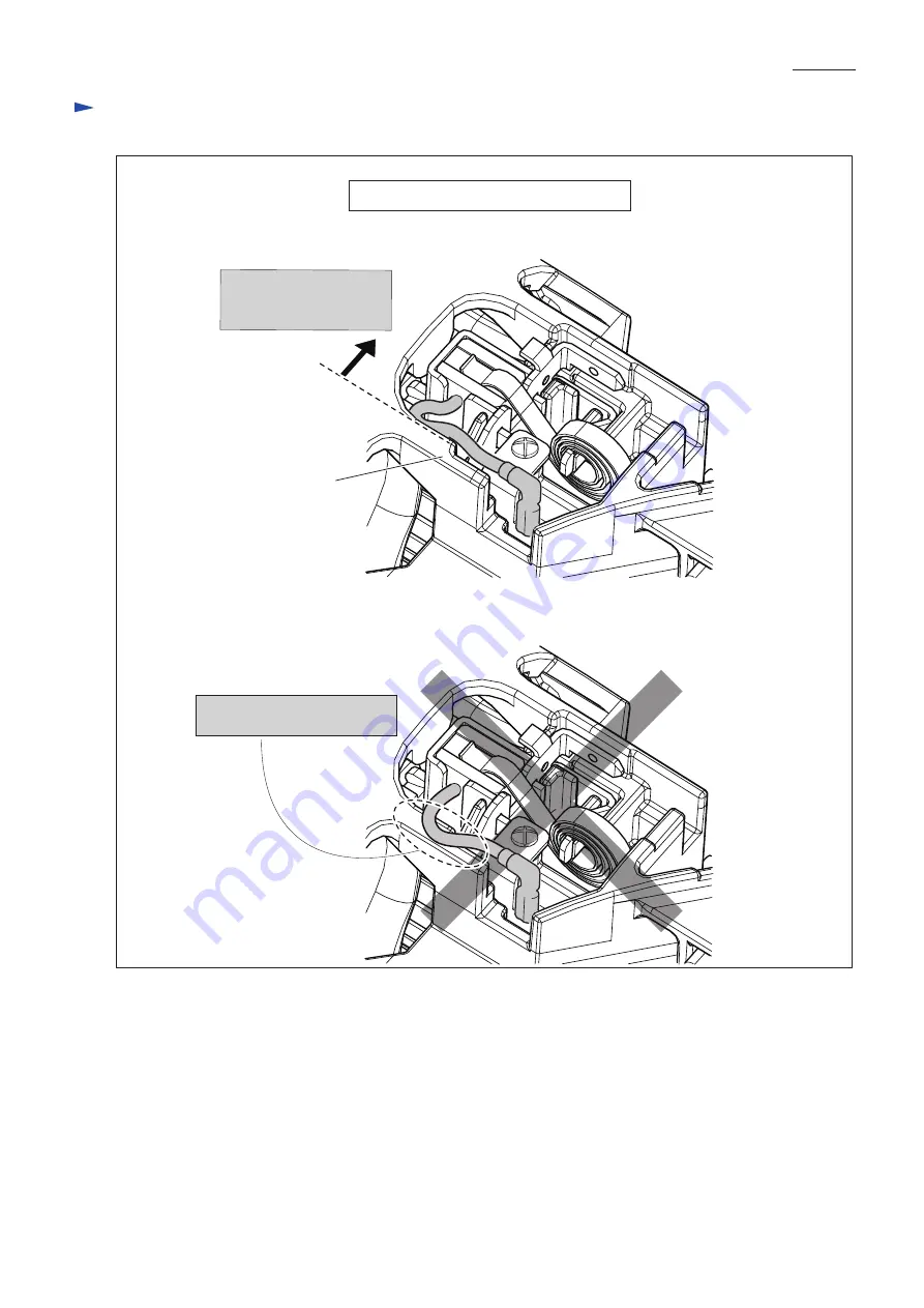
iring diagram
Wiring of Carbon brush’s pigtail
P 1
2
/ 1
Fig. D-5
Do not route Pigtail on any rib as designated with the circle.
Put Pigtail into the space betwwen Rib and Brush holder to avoid pinching.
Rib
Page 1: ...d control and better maneuverability Model JS1601 is designed mainly for straight cutting and JS1000 for curve cutting The different parts between JS1601 and JS1000 are Center blade and Side blades Center blade Side blade L Side blade R Hex wrench 3 1 Thickness gauge Feeler gauge 1 for JS1601 1 diameter at barrel 2 width at tool head including the protruding portion of the vents Weight according t...
Page 2: ...And then remove Shoulder pin 7 from Gear housing complete Fig 2 18 17 3g Rod a little Pin 5 33 Center blade Dust cover Shoulder pin 7 4x50 Tapping Screw 4pcs 1 Remove 4x50 Tapping screws and separate Crank housing from Gear housing 2 Remove Stop ring E 4 from the left end of Shoulder pin 7 3 Remove Shoulder pin 7 which secures Center blade Shoulder pin 7 Stop ring E 6 Stop ring E 4 Link 18 17 25 S...
Page 3: ...de can be removed from Link together with Dust cover 3 Remove Center blade from the slit of Dust cover Center blade Slit of Dust cover Height Width Note It has to be longer than height Pin 5 Flat washer 5 Fig 4 Link Dust cover 3 Assemble Washers and Shoulder pin 7 as illustrated in Fig 6 4 Adjust the clearance between Center blade and Side blade referring to Adjusting the Blade clearance 1 Insert ...
Page 4: ...de section as illustrated in Fig 2 Fig 3 2 Crank shaft section can be disassembled as illustrated in Fig 8 9 and 10 Fig 8 1R269 Fig 9 Fig 10 Remove Crank shaft section from Rod of Center blade section Rod Ball bearing 627ZZ Ball bearings 627ZZ and 696ZZ can be removed with 1R269 Remove Flat washer 7 from Crank shaft Center blade section Crank shaft section Ball bearing 696ZZ Ball bearing 6000ZZ Fl...
Page 5: ...mature s commutator to protect the Commutator against scratching by Carbon brush as illustrated in Fig 11 2 Disassemble Armature as illustrated in Figs 12 and 13 Rear cover Gear housing complete Crank housing complete Motor housing Ball bearing 608ZZ Ball Bearing 608ZZ and Ball bearing 607ZZ can be removed with 1R269 Ball bearing 607ZZ Insulation washer Labyrinth rubber ring 19 Motor housing Armat...
Page 6: ...t from Motor housing Blocking Switch knob to OFF position by inerting 1R281 push Switch lever strongly toward the 1R281 Only Switch lever can be moved while Switch konb can not move because of 1R281 The linkage of Switch knob is disconnected from Switch lever Consequently Switch knob can be removed Switch lever Switch lever 1R281 Switch knob Switch Switch knob Switch lever Repair P 6 12 Fig 16 Ass...
Page 7: ...nk housing And remove Armature from Motor housing as illustrated in Fig 11 3 After removing Baffle plate make preparation for removing Field as illustrated in Fig 18 4 Remove Field from Motor housing as illustrated in Fig 19 DISASSEMBLING 4x70 Tapping screw 2pcs Gear housing complete Crank housing complete Motor housing 4x50 Tapping screws 4pcs Baffle plate Spacer Fig 18 Fig 19 1 Strike Crank hous...
Page 8: ... Thickness mm Clearance mm between Center and Side blades Combination of Leaves of 1R366 M6X10 Hex socket head set screw Fig 22 Leaves of 1R366 selected from the table in Fig 20 Hex wrench 3 set on M4x25 Hex socket head bolt on Switch knob side Inserting Leaves of 1R366 between Center blade and Side blades adjust the clearance by turning M4x25 Hex socket head bolt on Switch knob side with Hex wren...
Page 9: ...lor index of lead wires sheath Black Red Fig D 1 Fig D 2R Fig D 2F Blue Lead wire is used for some countries Brown Lead wire is used for some countries Switch Noise suppressor Noise suppressor is not used for some countries ON OFF Button Connect Lead wires of Power supply cord to Switch terminal approaching from ON OFF Button side The protruding portion interferes with Switch in assembling to Swit...
Page 10: ...t Left Switch knob side Left Switch knob side Wiring of Field lead wires Field lead wires red Field lead wires red Motor housing Motor housing Switch knob Left Right Facing the connecting portion of long Lead wire red to left insert Field into Motor housing Switch knob Connecting portion of long Lead wire red Left Right Fig D 3 ...
Page 11: ...ush holder under the Rib belly side Power Supply Cord Boss for 4x18 Tapping screw Boss for 4x18 Tapping screw Put Lead wires of Power supply cord between Ribs Put sag portion of Lead wire of Power supply cord in this place Noise Suppressor Be careful not to pinch Field lead wire black to be connected to Brush holder with Rear cover Tighten the Field lead wires in Motor housing Noise suppressor ...
Page 12: ...iring diagram Wiring of Carbon brush s pigtail P 12 12 Fig D 5 Do not route Pigtail on any rib as designated with the circle Put Pigtail into the space betwwen Rib and Brush holder to avoid pinching Rib ...