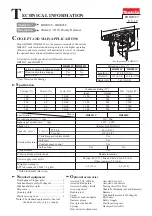
background image

P 1

0

/ 1

3

R

epair

DISASSEMBLING

Fig. 21

Fig. 20

Fig. 22

Fig. 23

Fig. 24

(1) Disassemble Motor housing section, Gear housing section and Inner housing section. As for HR2601, remove two 

      M4x12 Hex socket head bolts. And then separate Counter weight section from Inner housing complete. (

Fig. 20

)

(2) Remove two M4x16 Hex socket head bolts with hex wrench 3 and 1R228. (

Fig. 21)


      Then pull Swash bearing section out of  Inner housing complete. (

Fig. 22

)

(3) Remove Ball bearing 606ZZ from Gear housing complete using the removed Swash bearing section. (

Fig. 23

)

(4) Receive Clutch cam B on 1R035 and press Spur gear 10 out of Clutch cam B.

     The swash bearing section can be removed as drawn in 

Fig. 24.

Push Piston cylinder into Inner housing 

complete to tilt Swash bearing 10.

Pull Swash bearing section horizontally 

with Swash bearing 10 kept tilted, and 

remove the pole of Swash bearing 10 

toward the tilted direction.

Swash bearing section

(

Note

: Ball bearing 606ZZ is left in Gear housing complete.)

Swash bearing 10

[3] DISASSEMBLY/ASSEMBLY

[3]-7. Swash bearing section

M4x16 Hex socket 

head bolt (2 pcs.)

M4x12 Hex socket 

head bolt (2 pcs.)

Note

: These are thread 

           locking screws. 

           Do not reuse them without applying 

           ThreeBond 1321B/ 1342 or Loctite 242..

Inner housing complete

Insert shaft portion of Spur gear 10

to the hole of Ball bearing 606ZZ, 

and tilt it back and forth.  

Tap Gear housing complete with plastic hammer.

Ball bearing 606ZZ is removed together with

Swash bearing section.  

Piston cylinder

Ball bearing 606ZZ

in Gear housing 

complete

Ball bearing 606ZZ

Plate

Pin 6

Weight holder guide

 For HR2601 only

Counter weight

Spur gear 10 Clutch cam B Swash bearing 10

Flat washer 8

Swash bearing

section

Bearing retainer

Bearing box Ball bearing 608ZZ

Helical

gear 26

Summary of Contents for HR2600

Page 1: ...on with Hammering No Yes AVT 1 80 3 1 8 13 1 2 32 1 1 4 Yes No LED Job light Round shank bits can also be used by replacing the factory mounted chuck with Quick change drill chuck keyless PRODUCT P 1 13 Model Operation Mode LED Chuck type 2 modes Rotation only Rotation with hammering 3 modes Rotation only Rotation with hammering Hammering only No No 26mm Capacity 23mm 23mm 26mm No No Adapted for S...

Page 2: ...TCT hammer drill bits Taper shank adaptor Cotter Core bits Center bits Core bit adaptor Rod Drill chuck ass y Chuck adapter assembly Drill chuck S13 Chuck key S13 Tool holder set Scraper assembly Waterproof cover Quick change drill chuck keyless Dust cups 5 and 9 Hose Joint 25 Dust cup set Plastic carrying case Hammer grease 30g Bit grease Depth gauge Blow out bulb Safety goggles Bull points Cold ...

Page 3: ...head bolt Ring spring setting tool A 1R164 assembling Oil seal 25 Bearing setting pipe 20 12 2 1R028 removing Helical gear 26 Pipe 30 1R232 assembling Oil seal 25 Round bar for arbor 30 100 1R252 removing Oil seal 25 V block 1R258 assembling Oil seal 25 Bearing extractor 1R269 removing Ball bearing 6000LLB 627DDW Ring spring 26 setting tool B 1R273 removing Cup sleeve Ball bearing 6806LLU Round ba...

Page 4: ...e O ring 9 Tool holder complete 20 21 23 26 28 29 30 42 36 Pin 6 Piston joint 44 45 46 47 56 58 64 65 70 71 32 1 30 Portion that contacts Spur gear 51 Pins 6 30 Portion that contacts Spur gear 51 Pins 6 16 Compression spring 20 e Gear portion f Portion that contacts 58 Swash bearing 10 Gear portion that engages with Armature gear shaft Inside that contacts 48 Piston joint 38 Impact bolt Entire sur...

Page 5: ...d 4 Remove two Steel balls 7 0 while pressing down Ring 21 Fig 4 Ring 21 Guide washer and Conical compression spring 21 29 are removed Fig 2 Fig 3 Fig 5 Fig 4 ASSEMBLING Assemble in the reverse order of disassembly Refer to Fig 5 for the directions of the components Cap 35 Ring spring 14 black Ring spring 15 silver Flat washer 17 1R003 1R212 Ring 21 Guide washer Conical compression spring 21 29 St...

Page 6: ...e REPLACING 1 Remove three 4x18 Tapping screws and Handle cover 2 Slide Brush holder unit to the best position to repair and move the arms of Spiral springs aside then separate Carbon brushes from Commutator Fig 9 3 Remove four 4x30 Tapping screws then separate Motor housing from Gear housing complete Armature is left on Gear housing at that time Fig 10 Note Do not lose Wave washer 15 on the botto...

Page 7: ...mplete Fig 12 6 Compress Compression spring 32 Fig 13 then separate Spiro lock washer 30 from Tool holder complete by sliding a thin slotted screwdriver from the upper end as drawn in Fig 14 The components are disassembled Fig 15 Fig 13 Fig 12 Fig 14 Fig 15 Fig 11 Spiro lock washer 30 Tool holder complete Steel ball 4 4 pcs Pin 6 6 pcs Driving flange Compression spring 31 Tool holder complete Spur...

Page 8: ...oove of Tool holder complete 4 The components are removed by tapping with phillips screwdriver and plastic hammer from bit installation side of Tool holder complete Fig 17 Fig 16 Fig 17 HR2600 HR2601 Sleeve 9A Sleeve 9B Inner housing complete side Bit installation side Inner housing complete side Bit installation side Cushion ring 12 O ring case A O ring case B O ring 9 O ring 9 Ring spring 28 Rin...

Page 9: ...les of Tool holder complete 2 Push Ring spring 28 into the inner groove of Tool holder complete as drawn in Fig 19 Note Do not reuse the removed Ring spring 28 if it is deformed or damaged Piston cylinder as a jig Piston cylinder as a jig Tool holder complete end gap hole Inner groove of Tool holder complete Ring spring 28 O ring case A HR2600 HR2601 Note These components are directional hole 3 DI...

Page 10: ...tion horizontally with Swash bearing 10 kept tilted and remove the pole of Swash bearing 10 toward the tilted direction Swash bearing section Note Ball bearing 606ZZ is left in Gear housing complete Swash bearing 10 3 DISASSEMBLY ASSEMBLY 3 7 Swash bearing section M4x16 Hex socket head bolt 2 pcs M4x12 Hex socket head bolt 2 pcs Note These are thread locking screws Do not reuse them without applyi...

Page 11: ...riker with O ring 17 5 to Piston cylinder Refer to Fig 1 3 DISASSEMBLY ASSEMBLY 3 7 Swash bearing section cont The center is projected higher than that of the reverse Face the projection to Bearing retainer Bearing retainer Bearing box with Ball bearing 608ZZ Helical gear 26 3 8 How to assembly of Piston cylinder section to Swash bearing section Viewed from Swash bearing 10 side The wrong installa...

Page 12: ...ig 28 Note Be sure to put Makita grease RB No 00 to the specific portions Fig 1 Fig 28 Repair P 12 13 O ring 17 5 213258 4 Ring spring 14 233989 9 Cap 35 286288 8 Ring spring 15 233992 0 Rubber washer 16 424364 2 O ring 9 213073 6 Ring spring 28 233979 2 Steel ball 7 2 pcs 216022 2 HR2601 HR2600 Cushion ring 12 424267 0 ...

Page 13: ...y cord Strain relief Switch Fix white lead wire in this lead wire holder Fix black lead wire in this lead wire holder Lead wires black white must be tight between Brush holder unit and Lead wire holders Strain relief To comply with the electromagnetic compatibility requirement Switch equipped with Noise suppressor is used for some countries ...

Reviews: