background image

24 ENGLISH

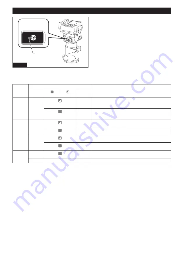
Description of the wireless activation lamp status

1

Fig.82

►    

1.

 Wireless activation lamp

The wireless activation lamp shows the status of the wireless activation function. Refer to the table below for the 

meaning of the lamp status.

Status

Wireless activation lamp

Description

Color


On


Blinking

Duration

Standby

Blue

2 hours

The wireless activation of the vacuum cleaner is available. The 

lamp will automatically turn off when no operation is performed 

for 2 hours.

When 

the tool is 

running.

The wireless activation of the vacuum cleaner is available and the 

tool is running.

Tool 

registration

Green

20 seconds Ready for the tool registration. Waiting for the registration by the 

vacuum cleaner.

2 seconds

The tool registration has been finished. The wireless activation 

lamp will start blinking in blue.

Cancelling 

tool 

registration

Red

20 seconds Ready for the cancellation of the tool registration. Waiting for the 

cancellation by the vacuum cleaner.

2 seconds

The cancellation of the tool registration has been finished. The 

wireless activation lamp will start blinking in blue.

Others

Red

3 seconds The power is supplied to the wireless unit and the wireless activa-

tion function is starting up.

Off

-

-

The wireless activation of the vacuum cleaner is stopped.

Summary of Contents for GTR01

Page 1: ...INSTRUCTION MANUAL MANUAL DE INSTRUCCIONES Cordless Trimmer Recortadora Inalámbrica GTR01 IMPORTANT Read Before Using IMPORTANTE Lea antes de usar ...

Page 2: ... flammable liquids gases or dust Power tools create sparks which may ignite the dust or fumes 3 Keep children and bystanders away while operating a power tool Distractions can cause you to lose control Electrical Safety 1 Power tool plugs must match the outlet Never modify the plug in any way Do not use any adapter plugs with earthed grounded power tools Unmodified plugs and matching outlets will ...

Page 3: ...ition that may affect the power tool s operation If dam aged have the power tool repaired before use Many accidents are caused by poorly maintained power tools 6 Keep cutting tools sharp and clean Properly maintained cutting tools with sharp cutting edges are less likely to bind and are easier to control 7 Use the power tool accessories and tool bits etc in accordance with these instructions tak i...

Page 4: ...you are working with SAVE THESE INSTRUCTIONS WARNING DO NOT let comfort or familiarity with product gained from repeated use replace strict adherence to safety rules for the subject product MISUSE or failure to follow the safety rules stated in this instruction manual may cause serious personal injury Symbols The followings show the symbols used for tool volts direct current no load speed revoluti...

Page 5: ...se the wireless unit to rain or wet conditions 5 Do not use the wireless unit in places where the temperature exceeds 50 C 122 F 6 Do not operate the wireless unit in places where medical instruments such as heart pace makers are nearby 7 Do not operate the wireless unit in places where automated devices are nearby If oper ated automated devices may develop malfunction or error 8 Do not operate th...

Page 6: ... tool causing injury to you or someone around you CAUTION Do not install the battery cartridge forcibly If the cartridge does not slide in easily it is not being inserted correctly Indicating the remaining battery capacity Press the check button on the battery cartridge to indi cate the remaining battery capacity The indicator lamps light up for a few seconds 1 2 Fig 2 1 Indicator lamps 2 Check bu...

Page 7: ... button again The tool turns into the standby mode To turn off the tool press the lock unlock button in the standby mode 1 2 Fig 3 1 Lock unlock button 2 Start stop button NOTE If the tool is left for 10 seconds without any operation in the standby mode the tool automatically turns off and the lamp goes off NOTE You can also stop and turn off the tool by pressing the lock unlock button while the t...

Page 8: ...ery cartridge is removed before carrying out any work on the tool Installing or removing trimmer bit NOTICE Do not tighten the collet nut without installing a trimmer bit or the collet cone may break Insert the trimmer bit all the way into the collet cone Press the shaft lock and tighten the collet nut with the wrench 1 2 3 4 5 Fig 6 1 Shaft lock 2 Loosen 3 Tighten 4 Wrench 5 Collet nut You can al...

Page 9: ...in the figure When using the trimmer base resin loosen or tighten the thumb nut instead of opening or closing the lock lever Align the rack on the tool with the spur gear on the trimmer base 1 3 2 Fig 11 1 Thumb nut 2 Rack 3 Spur gear 3 Attach the dust nozzle to the trimmer base and then tighten the thumb screw 2 1 Fig 12 1 Dust nozzle 2 Thumb screw Fig 13 To remove the base follow the installatio...

Page 10: ...ion procedure in reverse Installing or removing the offset base Optional accessory 1 Press the shaft lock then loosen the collet nut 1 2 3 Fig 15 1 Collet nut 2 Shaft lock 3 Wrench 2 Remove the collet nut and the collet cone 1 2 Fig 16 1 Collet nut 2 Collet cone 3 Install the pulley onto the tool by pressing the shaft lock and tightening the pulley with the wrench 1 2 3 Fig 17 1 Wrench 2 Pulley 3 ...

Page 11: ...ley 2 Belt 7 Close the lock lever 1 Fig 21 1 Lock lever 8 Attach the base plate by tightening the screws 1 Fig 22 1 Base plate 9 Insert the collet cone and the trimmer bit into the offset base and then tighten the collet nut 1 2 3 Fig 23 1 Trimmer bit 2 Collet nut 3 Collet cone 10 Insert the hex wrench into the hole of the offset base and then tighten the collet nut with the wrench 1 2 3 Fig 24 1 ...

Page 12: ...e the base follow the installation procedure in reverse Installing or removing the parallel ruler on the plunge base Optional accessory Insert the guide bars into the holes in the plunge base and then tighten the wing bolts To remove the ruler follow the installation procedure in reverse 1 2 Fig 27 1 Wing bolt 2 Guide bar Installing or removing the dust nozzle on the plunge base Insert the dust no...

Page 13: ...ose the lock lever 1 Fig 31 1 Hex nut Adjusting cutting depth with the plunge base Optional accessory 1 Place the tool on the flat surface 2 Select the stopper screw by rotating the stopper base 1 2 Fig 32 1 Stopper screw 2 Stopper base 3 Loosen the fixing nut then pull up the stopper pole while pressing the feed button 1 2 3 Fig 33 1 Stopper pole 2 Fixing nut 3 Feed button 4 Push down the tool un...

Page 14: ...pper pole while pressing the feed button 1 2 Fig 37 1 Stopper pole 2 Feed button 8 To perform fine adjustment of the cutting depth turn the dial on the stopper pole so that it indicates 0 1 Fig 38 1 Dial 9 Turn the head of the stopper pole to obtain the desired depth To increase the depth turn the head counterclockwise To decrease the depth turn the head clockwise The depth changes by 1 mm 3 64 pe...

Page 15: ... of workpiece and depth of cut Moving the tool forward too fast may cause a poor quality of cut or damage to the trimmer bit or motor Moving the tool forward too slowly may burn and mar the cutting surface When using the trimmer shoe the straight guide or the trimmer guide be sure to keep it on the right side in the feed direction This will help to keep it flush with the side of the workpiece 1 3 ...

Page 16: ...straight board to the work piece and use it as a guide against the trimmer base Feed the tool in the direction of the arrow A Fig 48 Using the straight guide for circular work For circular work assemble the straight guide as shown in the figures The minimum and maximum radius of circles to be cut distance between the center of circle and the center of trimmer bit are as follows Minimum 70 mm 2 3 4...

Page 17: ...2 Fig 52 1 Base plate 2 Templet guide 3 Place the tool on the templet and move the tool so that the templet guide slides along the side of the templet Fig 53 NOTE The actual cut size on the workpiece is slightly different from the templet The difference is the dis tance X between the trimmer bit and the outside of the templet guide The distance X can be calculated by using the following equation D...

Page 18: ...t base The tilt base is used for trimming the edge of laminate sheet or similar materials The tilt base is convenient for chamfering Loosen the wing screws then tilt the tool at the desired angle and then tighten the wing screws Firmly clamp a straight board to the workpiece and use it as a guide against the tilt base Feed the tool in the direction of the arrow 1 Fig 59 1 Wing screw Using the tilt...

Page 19: ...cessory for more stability 1 Loosen the screws on the offset base plate then remove the offset base plate from the offset base 1 2 Fig 62 1 Offset base plate 2 Trimmer base plate 2 Attach the offset base plate to the trimmer base by tightening the screws 3 Attach the grip attachment and the bar type grip to the offset base plate by tightening the screws 1 2 Fig 63 1 Bar type grip 2 Grip attachment...

Page 20: ...e desired distance tighten the wing nut 1 Fig 66 1 Wing nut 3 Operate the tool in the same way as the straight guide for the trimmer base Fig 67 Using the templet guide Optional accessory 1 Loosen the screws on the base and remove them Place the templet guide on the base and then tighten the screws 1 2 Fig 68 1 Screw 2 Templet guide 2 Operate the tool in the same way as the templet guide for the t...

Page 21: ...aner automatically along with the switch operation of the tool Fig 73 To use the wireless activation function prepare follow ing items A wireless unit optional accessory A vacuum cleaner which supports the wireless activation function The overview of the wireless activation function setting is as follows Refer to each section for detail procedures 1 Installing the wireless unit 2 Tool registration...

Page 22: ...wireless activation function is required for the tool registration NOTE Finish installing the wireless unit to the tool before starting the tool registration NOTE During the tool registration do not pull the switch trigger or turn on the power switch on the vacuum cleaner NOTE Refer to the instruction manual of the vacuum cleaner too If you wish to activate the vacuum cleaner along with the switch...

Page 23: ...tch on the vacuum cleaner to AUTO 1 Fig 80 1 Stand by switch 4 Push the wireless activation button on the tool briefly The wireless activation lamp will blink in blue 2 1 Fig 81 1 Wireless activation button 2 Wireless activation lamp 5 Turn on the tool Check if the vacuum cleaner runs while the tool is operating To stop the wireless activation of the vacuum cleaner push the wireless activation but...

Page 24: ...vacuum cleaner is available and the tool is running Tool registration Green 20 seconds Ready for the tool registration Waiting for the registration by the vacuum cleaner 2 seconds The tool registration has been finished The wireless activation lamp will start blinking in blue Cancelling tool registration Red 20 seconds Ready for the cancellation of the tool registration Waiting for the cancellatio...

Page 25: ...nd then become red After that press the wireless activation button on the tool in the same way 1 2 1 2 Fig 84 1 Wireless activation button 2 Wireless activation lamp If the cancellation is performed successfully the wire less activation lamps will light up in red for 2 seconds and start blinking in blue NOTE The wireless activation lamps finish blinking in red after 20 seconds elapsed Press the wi...

Page 26: ... the power button on the vacuum cleaner is turned on Push the wireless activation button briefly and perform the tool registration cancellation procedures again The tool registration procedures for the tool or vacuum cleaner have not finished Perform the tool registration procedures for both the tool and the vacuum cleaner at the same timing Radio disturbance by other appliances which generate hig...

Page 27: ...SAFETY and RELIABILITY repairs any other maintenance or adjustment should be performed by Makita Authorized or Factory Service Centers always using Makita replacement parts TRIMMER BITS Optional accessory Straight bit D L1 L2 A Fig 85 D A L1 L2 6 20 50 15 6 6 50 18 6 8 50 18 8 8 60 25 1 4 20 50 15 1 4 6 50 18 1 4 8 50 18 Unit mm U grooving bit L2 L1 D A R Fig 86 D A L1 L2 R 6 6 50 18 3 1 4 6 50 18...

Page 28: ...ig 89 D A L1 L2 L3 L4 6 6 70 40 12 14 8 8 80 55 20 25 1 4 6 70 40 12 14 Unit mm Corner rounding bit Fig 90 D A1 A2 L1 L2 L3 R 6 25 9 48 13 5 8 6 20 8 45 10 4 4 1 4 25 9 48 13 5 8 1 4 20 8 45 10 4 4 Unit mm Chamfering bit Fig 91 D A L1 L2 L3 θ 6 23 46 11 6 30 6 20 50 13 5 45 6 20 49 14 2 60 1 4 23 46 11 6 30 1 4 20 48 13 5 45 1 4 20 49 14 2 60 Unit mm ...

Page 29: ...L1 L2 θ 8 12 50 9 30 8 14 5 55 10 35 8 14 5 55 14 5 23 1 4 12 50 9 30 1 4 14 5 55 10 35 1 4 14 5 55 14 5 23 Unit mm Ball bearing flush trimming bit Fig 94 D A L1 L2 6 10 50 20 1 4 10 50 20 Unit mm Ball bearing beading bit Fig 95 D A1 A2 A3 L1 L2 L3 R 6 20 12 8 40 10 5 5 4 6 26 12 8 42 12 4 5 7 1 4 20 12 8 40 10 5 5 4 1 4 26 12 8 42 12 4 5 7 Unit mm ...

Page 30: ... 6 26 8 42 12 45 6 20 8 41 11 60 1 4 26 8 42 12 45 1 4 20 8 41 11 60 Unit mm Ball bearing cove beading bit Fig 98 D A1 A2 A3 A4 L1 L2 L3 R 6 20 18 12 8 40 10 5 5 3 6 26 22 12 8 42 12 5 5 1 4 20 18 12 8 40 10 5 5 3 1 4 26 22 12 8 42 12 5 5 Unit mm Ball bearing roman ogee bit Fig 99 D A1 A2 L1 L2 L3 R1 R2 6 20 8 40 10 4 5 2 5 4 5 6 26 8 42 12 4 5 3 6 1 4 20 8 40 10 4 5 2 5 4 5 1 4 26 8 42 12 4 5 3 6...

Page 31: ...regard ing these accessories ask your local Makita Service Center Straight and groove forming bits Edge forming bits Laminate trimming bits Straight guide assembly Trimmer guide assembly Trimmer base assembly Trimmer base assembly resin Tilt base assembly Plunge base assembly Offset base assembly Grip attachment Templet guide Collet cone Wrench 13 Wrench 22 Wireless unit Makita genuine battery and...

Page 32: ...00 1 Trimmer base metal 2 Trimmer base resin Clear visibility of the cut 3 Tilt base 4 Offset base 5 Plunge base 6 Grip attachment 7 Templet guide 8 Straight guide 9 Trimmer guide 10 Trimmer shoe Enables accurate edge works Use with parts of the trimmer guide 11 Dust nozzle 12 Base plate metal 13 Square base plate base plate of the tilt base 14 Offset base plate base plate of the offset base By us...

Page 33: ...de rails 28 Clamp standard type For fixation of the guide rail 29 Clamp quick type For fixation of the guide rail 30 Seat Repair parts of the guide rail for upper plastic tape 31 Rubber seat Repair parts of the guide rail for lower rubber tape 32 Position seat Repair parts of the guide rail for position seat 25 24 30 28 29 31 32 Fig 101 MAKITA LIMITED WARRANTY Please refer to the annexed warranty ...

Page 34: ...éctrica se refiere a su herramienta eléctrica de funcionamiento con conexión a la red eléctrica con cableado eléctrico o herramienta eléctrica de funcionamiento a batería inalámbrica Seguridad en el área de trabajo 1 Mantenga el área de trabajo limpia y bien ilu minada Las áreas oscuras o desordenadas son propensas a accidentes 2 No utilice las herramientas eléctricas en atmósferas explosivas tal ...

Page 35: ...lvo puede reducir los riesgos relacionados con el polvo 8 No permita que la familiaridad adquirida debido al uso frecuente de las herramientas haga que se sienta confiado e ignore los prin cipios de seguridad de las herramientas Un descuido podría ocasionar una lesión grave en una fracción de segundo 9 Utilice siempre gafas protectoras para prote ger sus ojos de lesiones al usar herramientas eléct...

Page 36: ...ciones para el uso y cuidado Advertencias de seguridad para la recortadora inalámbrica 1 Utilice abrazaderas o algún otro medio práctico para asegurar y sujetar la pieza de trabajo a una plataforma estable Sostener la pieza de trabajo con la mano o contra su cuerpo produce inestabili dad y puede ocasionar la pérdida de control 2 Sujete la herramienta eléctrica solamente por las superficies de asim...

Page 37: ...uso en el caso de que esté dañado seriamente o ya no sirva en absoluto El cartucho de batería puede explotar si se tira al fuego 8 No clave corte aplaste lance o deje caer el cartucho de batería ni golpee un objeto sólido contra el cartucho de batería Dicha acción podría resultar en un incendio calor excesivo o en una explosión 9 No use una batería dañada 10 Las baterías de ión de litio están suje...

Page 38: ...suario 10 La unidad inalámbrica es un instrumento de precisión Tenga cuidado de no dejar caer ni golpear la unidad inalámbrica 11 Evite tocar la terminal de la unidad inalámbrica con las manos descubiertas o con materiales metálicos 12 Retire siempre la batería del producto al insta lar en él la unidad inalámbrica 13 Cuando abra la tapa de la ranura evite el lugar donde el polvo y el agua puedan i...

Page 39: ...de batería hasta que el indicador rojo no pueda verse Si no podría accidentalmente salirse de la herramienta y caer al suelo causando una lesión a usted o alguien a su alrededor PRECAUCIÓN No instale el cartucho de batería a la fuerza Si el cartucho no se desliza al interior fácilmente se debe a que no está siendo insertado correctamente Indicación de la capacidad restante de la batería Oprima el ...

Page 40: ...ervi cio Makita Accionamiento del interruptor Para encender la herramienta oprima el botón de bloqueo desbloqueo La herramienta se pondrá en el modo en espera Para arrancar la herramienta oprima el botón de encendido apagado en el modo en espera Para detener la herramienta oprima el botón de encen dido apagado nuevamente La herramienta se pondrá en el modo en espera Para apagar la herramienta opri...

Page 41: ...y le permite comenzar la siguiente operación antes Si de manera consistente la herramienta no logra detener la fresa de la recortadora después de que se apaga el interruptor lleve la herramienta a un centro de servicio Makita para que le den mantenimiento MONTAJE PRECAUCIÓN Asegúrese siempre de que la herramienta esté apagada y el cartucho de batería haya sido extraído antes de realizar cualquier ...

Page 42: ...la base de la recor tadora luego inserte la herramienta en la base de la recortadora alineando la ranura en la herramienta con la protuberancia en la base de la recortadora 2 Cierre la palanca de bloqueo 1 Fig 10 1 Palanca de bloqueo NOTA Puede usar la base de la recortadora resina como accesorio opcional según se muestra en la figura Al usar la base de la recortadora resina afloje o apriete la tu...

Page 43: ... en la herramienta con la protuberancia en la base de inclinación 2 Cierre la palanca de bloqueo 1 Fig 14 1 Palanca de bloqueo Para extraer la base siga el procedimiento de instala ción en orden inverso Instalación o extracción de la base descentrada Accesorio opcional 1 Presione el bloqueo del eje y luego afloje la tuerca de sujeción 1 2 3 Fig 15 1 Tuerca de sujeción 2 Bloqueo de eje 3 Llave 2 Re...

Page 44: ... la correa en la polea con un objeto como un destornillador plano girando la correa manualmente 2 1 Fig 20 1 Polea 2 Correa 7 Cierre la palanca de bloqueo 1 Fig 21 1 Palanca de bloqueo 8 Fije la placa de base apretando los tornillos 1 Fig 22 1 Placa de base 9 Inserte el cono de sujeción y la fresa de la recor tadora en la base descentrada y luego apriete la tuerca de sujeción 1 2 3 Fig 23 1 Fresa ...

Page 45: ...rio opcional 1 Abra la palanca de bloqueo de la base de inmer sión luego inserte la herramienta en la base de inmer sión hasta el fondo alineando la ranura en la herra mienta con la protuberancia en la base de inmersión 2 Cierre la palanca de bloqueo 1 Fig 26 1 Palanca de bloqueo Para extraer la base siga el procedimiento de instala ción en orden inverso Instalación o extracción de la regla parale...

Page 46: ...a la base de la herramienta hacia arriba o hacia abajo girando el tornillo de ajuste Después del ajuste cierre la palanca de bloqueo firmemente 1 2 Fig 30 1 Palanca de bloqueo 2 Tornillo de ajuste AVISO Si la herramienta no queda asegurada después de cerrar la palanca de bloqueo apriete la tuerca hexagonal y luego cierre la palanca de bloqueo 1 Fig 31 1 Tuerca hexagonal Ajuste de la profundidad de...

Page 47: ... indique 0 en la escala 1 Fig 36 1 Indicador de profundidad 7 Ajuste la profundidad de corte jalando hacia arriba la barra de tope mientras oprime el botón de alimentación 1 2 Fig 37 1 Barra de tope 2 Botón de alimentación 8 Para realizar un ajuste fino de la profundidad de corte gire el selector en la barra de tope de manera que éste indique 0 1 Fig 38 1 Selector 9 Gire la cabeza de la barra de t...

Page 48: ...eza de trabajo real se recomienda hacer un corte de prueba La velocidad de avance apropiada dependerá del tamaño de la fresa de la recortadora el tipo de pieza de trabajo y la profundidad de corte Si mueve la herramienta hacia adelante demasiado rápido podrá obtener un corte de mala calidad o dañar la fresa de la recortadora o el motor Si mueve la herramienta hacia delante muy despacio podría quem...

Page 49: ...para la guía recta o si el costado de la pieza de trabajo no es recto no podrá utilizarse la guía recta En este caso sujete firmemente una tabla recta a la pieza de trabajo y utilícela como guía contra la base de la recortadora Avance la herramienta en la dirección de la flecha A Fig 48 Uso de la guía recta para hacer un corte circular Para hacer un corte circular ensamble la guía recta tal como s...

Page 50: ...en el sentido de las manecillas del reloj 2 1 Fig 51 1 Clavo 2 Orificio central Uso de la guía de plantilla La guía de plantilla permite repetir un corte con los patrones de plantilla mediante el uso de una plantilla 1 Afloje los tornillos en la placa de base y luego retire la placa de base de la base de la recortadora 2 Coloque la guía de plantilla sobre la base y luego fije la placa de base apre...

Page 51: ...ía de recorte permite hacer los cortes curvados como chapas para muebles moviendo el rodillo guía a lo largo del costado de la pieza de trabajo Fig 55 1 Afloje el tornillo de fijación instale la guía de recorte en la base de la recortadora y luego apriete el tornillo de fijación 1 Fig 56 1 Tornillo de fijación 2 Afloje el tornillo de fijación y ajuste la distancia entre la fresa de la recortadora ...

Page 52: ...la recortadora 1 2 Fig 60 1 Placa de base de inclinación 2 Placa de base de la recortadora AVISO Utilice tornillos de la base de la recorta dora cuando instale la placa base de inclinación Los tornillos de la base de inclinación son más cortos que los tornillos de la base de la recortadora Uso de la herramienta con la base descentrada La base descentrada se utiliza para recortar el borde de hojas ...

Page 53: ...las empuñaduras con ambas manos durante la operación Opere la herramienta de la misma manera que la base de la recortadora Uso de la guía recta Accesorio opcional 1 Instale la guía recta en el sujetador de la guía apretando la tuerca de mariposa Inserte el sujetador de la guía en los orificios en la base de inmersión y luego apriete los pernos de mariposa 1 2 3 4 Fig 65 1 Perno de mariposa 2 Sujet...

Page 54: ... herra mienta con la regla paralela nivelada con el costado de la pieza de trabajo Fig 70 Si la distancia A entre el costado de la pieza de tra bajo y la posición de corte es muy ancha para la regla paralela o si el costado de la pieza de trabajo no es recto no podrá utilizarse la regla paralela En este caso sujete firmemente una tabla recta a la pieza de trabajo y utilícela como guía contra la ba...

Page 55: ...ería si llegan a introducirse en la ranura de la unidad inalámbrica AVISO Para evitar una avería a causa de la elec tricidad estática toque un material de descarga de electricidad estática tal como una pieza metá lica de la herramienta antes de levantar la unidad inalámbrica AVISO Cuando vaya a instalar la unidad inalám brica asegúrese siempre de que ésta sea inser tada en la dirección correcta y ...

Page 56: ... la aspiradora y la herramienta han sido conectadas exitosamente las luces indicadoras de activación inalámbrica se encenderán en verde durante 2 segundos y comenzarán a parpadear en azul NOTA Las luces indicadoras de activación inalámbrica terminarán parpadeando en verde después de un lapso de 20 segundos Oprima el botón de activación inalám brica en la herramienta mientras la luz indicadora de a...

Page 57: ...ripción del estado de la luz indicadora de activación inalámbrica 1 Fig 82 1 Luz indicadora de activación inalámbrica La luz indicadora de activación inalámbrica muestra el estado de la función de activación inalámbrica Consulte la tabla a continuación para ver qué significa el estado de la luz indicadora Estado Luz indicadora de activación inalámbrica Descripción Color Encendida Parpadeando Durac...

Page 58: ...ctivación inalámbrica en la herramienta de la misma manera 1 2 1 2 Fig 84 1 Botón de activación inalámbrica 2 Luz indica dora de activación inalámbrica Si la cancelación se realiza exitosamente las luces indi cadoras de activación inalámbrica se encenderán en rojo durante 2 segundos y comenzarán a parpadear en azul NOTA Las luces indicadoras de activación inalám brica terminarán parpadeando en roj...

Page 59: ...lada incorrectamente en la herramienta Instale la unidad inalámbrica correctamente La terminal de la unidad inalámbrica y o la ranura está sucia Retire con cuidado el polvo y la suciedad en la terminal de la unidad inalámbrica y limpie la ranura El interruptor de modo en espera en la aspiradora no está ajustado en AUTO Ajuste el interruptor de modo en espera en la aspiradora en AUTO No hay suminis...

Page 60: ...están lejos una de la otra fuera del rango de transmisión Acerque más la herramienta a la aspiradora La distan cia máxima de transmisión es de aproximadamente 10 m pero puede variar en función de las circunstancias La perturbación radioeléctrica generada por otros aparatos que emiten ondas de radio de alta intensidad Mantenga la herramienta y la aspiradora lejos de aparatos tales como dispositivos...

Page 61: ...0 mm 50 mm 15 mm 90 1 4 20 mm 50 mm 15 mm 90 Unidad mm Fresa de corte a ras con punta de taladro Fig 88 D A L1 L2 L3 6 mm 6 mm 60 mm 18 mm 28 mm 8 mm 8 mm 60 mm 20 mm 35 mm 1 4 6 mm 60 mm 18 mm 28 mm Unidad mm Fresa de corte doble a ras con punta de taladro Fig 89 D A L1 L2 L3 L4 6 mm 6 mm 70 mm 40 mm 12 mm 14 mm 8 mm 8 mm 80 mm 55 mm 20 mm 25 mm 1 4 6 mm 70 mm 40 mm 12 mm 14 mm Unidad mm ...

Page 62: ...5 6 mm 20 mm 49 mm 14 mm 2 mm 60 1 4 23 mm 46 mm 11 mm 6 mm 30 1 4 20 mm 48 mm 13 5 mm 45 1 4 20 mm 49 mm 14 mm 2 mm 60 Unidad mm Fresa de moldura de ensenada Fig 92 D A L1 L2 R 6 mm 20 mm 43 mm 8 mm 4 mm 6 mm 25 mm 48 mm 13 mm 8 mm 1 4 20 mm 43 mm 8 mm 4 mm 1 4 25 mm 48 mm 13 mm 8 mm Unidad mm Fresa con cola de milano θ θ θ D L2 L1 A Fig 93 D A L1 L2 θ 8 mm 12 mm 50 mm 9 mm 30 8 mm 14 5 mm 55 mm ...

Page 63: ...0mm 5 5mm 4 mm 1 4 26mm 12mm 8 mm 42mm 12mm 4 5mm 7 mm Unidad mm Fresa de redondeo de esquinas con rodamiento de balines Fig 96 D A1 A2 L1 L2 L3 R 6 mm 15 mm 8 mm 37 mm 7 mm 3 5 mm 3 mm 6 mm 21 mm 8 mm 40 mm 10 mm 3 5 mm 6 mm 1 4 15 mm 8 mm 37 mm 7 mm 3 5 mm 3 mm 1 4 21 mm 8 mm 40 mm 10 mm 3 5 mm 6 mm Unidad mm Fresa de biselado con rodamiento de balines Fig 97 D A1 A2 L1 L2 θ 6 mm 26 mm 8 mm 42 m...

Page 64: ...r otro accesorio o aditamento puede conllevar el riesgo de lesiones personales Utilice los accesorios o aditamentos solamente para su fin establecido Si necesita cualquier ayuda para más detalles en relación con estos accesorios pregunte a su centro de servicio local Makita Fresas rectas y de formación de ranuras Fresas de formación de bordes Fresas de recorte de laminados Conjunto de la guía rect...

Page 65: ...la recortadora resina Clara visibilidad del recorte 3 Base de inclinación 4 Base descentrada 5 Base de inmersión 6 Accesorio de la empuñadura 7 Guía de plantilla 8 Guía recta 9 Guía de recorte 10 Zapata de la recortadora Permite trabajos en el borde precisos Úselo con partes de la guía de recorte 11 Boquilla para polvo 12 Placa base metal 13 Placa base cuadrada placa base de la base de inclinación...

Page 66: ...zadera tipo estándar Para la fijación del carril guía 29 Abrazadera tipo rápido Para la fijación del carril guía 30 Asiento Para reparar las piezas del carril guía para la cinta plástica superior 31 Asiento de hule Para reparar las piezas del carril guía para la cinta de caucho inferior 32 Asiento de posición Para reparar las piezas del carril guía para el asiento de posición 25 24 30 28 29 31 32 ...

Page 67: ...67 ...

Page 68: ...ados por el lijado aserrado esmerilado taladrado y otras actividades de la construcción contienen sustancias químicas reconocidas por el Estado de California como causantes de cáncer defectos de nacimiento y otros peligros de reproducción Algunos ejemplos de estos productos químicos son plomo de pinturas a base de plomo sílice cristalino de ladrillos y cemento y otros productos de albañilería y ar...

Reviews: