Makita EM407MP Original Instruction Manual Download Page 14

14 ENGLISH

MAINTENANCE

WARNING:


Before inspecting or maintaining 

the equipment, switch off the motor and remove 

the spark plug cap or battery cartridge. 

Otherwise 

the cutting tool or other parts may move and result in 

serious injury.

WARNING:


When inspecting or maintaining 

the equipment, always put it down.

 Assembling or 

adjusting the equipment in an upright position may 

result in serious injury.

WARNING:


Follow the warnings and precau-

tions in the section for safety warnings and the 

instruction manual of the power unit.

NOTICE:


Never use gasoline, benzine, thinner, 

alcohol or the like. Discoloration, deformation or 

cracks may result.

To maintain product SAFETY and RELIABILITY, 

repairs, any other maintenance or adjustment should 

be performed by Makita Authorized or Factory Service 

Centers, always using Makita replacement parts.

Overall inspection

• 

Tighten loose bolts, nuts and screws.

• 

Check for damaged parts and blades. Ask our 

authorized service center to replace them if 

necessary.

Cleaning the tool

Clean the attachment by wiping off dust, dirt, or cut off 

grass with a dry cloth or one dipped in soapy water and 

wrung out. Remove the cut off grass or debris adhered 

to the cutter blade.

Dismounting the cutter blades

CAUTION:


Always wear gloves when dis-

mounting the cutter blades.

When cleaning, sharpening, or replacing the cutter 

blades, dismount them by the following procedure:

1.

  Remove the blade cover.

2.

  Set the box wrench onto the nut. Rotate the box 

wrench so that the hole in the lower blade aligns with 

the hole in the upper blade.
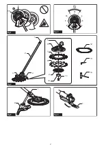
► 

Fig.10:


1.

 Box wrench 

2.

 Hole in the lower blade

Look into the hole in the lower blade to check if the 

correct hole in the upper blade is aligned. In the upper 

blade, there are pins and two types of holes; true circle 

and oval. Align the true circle hole in the upper blade 

with the hole in the lower blade and then insert the hex 

wrench into the holes.

► 

Fig.11:


1.

 Hole in the lower blade 

2.

 True circle hole 

in the upper blade 

3.

 Oval hole in the upper 

blade 

4.

 Pin

► 

Fig.12:


1.

 Lower blade 

2.

 Upper blade 

3.

 Hex 

wrench

NOTE:

 Choose the true circle hole in the upper blade 

by referring the following information:
• 

When you rotate the lower blade counterclock

-

wise, the true circle hole comes after the pin.

• 

When the oval hole is aligned with the hole in 

the lower blade, you can insert the hex wrench 

but there is a lot of backlash.

• 

When the pin is aligned with the hole in the 

lower blade, you can see the screw thread in 

the pin. In this case, you cannot insert the hex 

wrench fully.

CAUTION:


Do not put your fingers on the 

blade when rotating the box wrench.

 The blades 

rotate as you rotate the box wrench and it may cause 

personal injury.

CAUTION:


Always use the box wrench when 

aligning the holes in the upper and lower blades.

3.

  While inserting the hex wrench, turn the bolt clock-

wise using the box wrench to loosen the bolt.
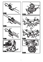
► 

Fig.13:


1.

 Box wrench 

2.

 Hex wrench

4.

  Remove the bolt, clamp washer, and the holder 

together with the lower blade.

► 

Fig.14:


1.

 Bolt 

2.

 Clamp washer 

3.

 Holder (for lower 

blade) 

4.

 Lower blade

5.

  While pushing the upper blade, rotate it counter-

clockwise to position the pin as shown in the figure. 

After that, lift the upper blade from the holder to remove.
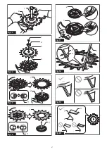
► 

Fig.15:


1.

 Upper blade 

2.

 Holder (for upper blade) 

3.

 Pin

6.

  Remove the lower blade. To remove, rotate the 

lower blade counterclockwise to position the pin as 

shown in the figure and then lift the lower blade from the 

holder.

► 

Fig.16:


1.

 Lower blade 

2.

 Holder (for lower blade) 

3.

 Pin

NOTICE:


After dismounting the cutter blades, 

keep the bolt, clamp washer, and the holder in 

place to avoid them from being lost.

NOTE:

 To install the cutter blades, refer to the section 

for replacing the cutter blades.

Removing jammed weeds

NOTICE:


Periodically remove jammed weeds 

and foreign objects between the cutter blades and 

in the holders.

 Using this attachment with weeds 

jammed inside may result in malfunction.

Dismount the cutter blades. Remove jammed weeds 

between the upper and lower blades. Also remove 

the jammed weeds in the holders, especially around 

the pins, using a brush. Be sure to clean the weeds 

adhered to the holder as shown in the figure.

► 

Fig.17:


1.

 Holder (for upper blade) 

2.

 Holder (for 

lower blade)

Clean the cutter blades with water and dry them com

-

pletely. After that, apply anti-rust oil.

Summary of Contents for EM407MP

Page 1: ...RAHAN ASAL 40 VI Phụ Kiện Kéo Cắt Cỏ Tròn TÀI LIỆU HƯỚNG DẪN GỐC 52 TH อุปกรณ ต อพ วงกรรไกรโรตารี ต นฉบับคู มือการใช งาน 63 ZHTW 剪式割草盤 原始操作手冊 77 KO 안전판 회전날 취급 설명서 88 PTBR Acessório tesoura rotativa MANUAL DE INSTRUÇÕES ORIGINAL 98 ES Accesorio de Tijeras Rotativas MANUAL DE INSTRUCCIONES ORIGINAL 110 FA چرخنده قیچی ضمیمه اصلی راهنمای دفترچه 130 AR الدوار المقص ملحق األصلي اإلرشادات دليل 138 ...

Page 2: ...11 1 Fig 1 12 1 2 3 4 11 10 9 8 Fig 2 1 2 3 5 6 7 8 9 10 11 12 13 14 4 Fig 3 1 2 Fig 4 1 Fig 5 2 ...

Page 3: ...1 2 3 Fig 6 1 Fig 7 Fig 12 3 1 2 Fig 8 Fig 9 1 2 Fig 10 1 1 2 2 3 4 Fig 11 1 2 3 Fig 12 3 ...

Page 4: ...1 2 Fig 13 1 2 3 4 Fig 14 1 2 3 Fig 15 2 1 3 Fig 16 1 2 Fig 17 40 40 1 2 4 3 Fig 18 Fig 19 1 2 3 Fig 20 4 ...

Page 5: ...1 2 3 Fig 21 1 2 3 Fig 22 1 2 3 Fig 23 1 2 4 3 Fig 24 2 1 Fig 25 1 2 Fig 26 1 Fig 27 Fig 28 5 ...

Page 6: ...1 Fig 29 Fig 30 6 ...

Page 7: ... attachment with non approved power unit Non approved combi nation may cause serious injury Symbols The following symbols are used on the attachment and this instruction manual Understand these definitions Take Particular care and attention Read the instruction manual Wear protective helmet eye and ear protection Protective gloves must be worn Wear sturdy boots with nonslip soles Steeltoed safety ...

Page 8: ...ional starting Ensure the switch is in the off position before connecting to power source and or battery pack picking up or carrying the tool Carrying power tools with your finger on the switch or energising power tools that have the switch on invites accidents 4 Remove any adjusting key or wrench before turning the power tool on A wrench or a key left attached to a rotating part of the power tool...

Page 9: ...nstructions and do not charge the battery pack or tool outside the temperature range specified in the instruc tions Charging improperly or at temperatures outside the specified range may damage the battery and increase the risk of fire Service 1 Have your power tool serviced by a qualified repair person using only identical replacement parts This will ensure that the safety of the power tool is ma...

Page 10: ...well ventilated area Operation in a confined or poorly ventilated area can result in death due to suffocation or carbon monoxide poisoning 3 Before starting make sure that the cutting tool has no contact with hard objects such as branches stones etc as the cutting tool will revolve when starting 4 If the cutting tool rotates at idle adjust the idle speed so that it stops at idle Otherwise uninten ...

Page 11: ...e unit and or operator to be propelled in any direc tion and possibly lose control of the unit resulting in serious injury Kickback can occur without warn ing if the blade snags stalls or binds and is more likely to occur in areas where it is difficult to see the material being cut Kickback occurs particularly when applying the blade segment between 11 and 1 o clock to solids bushes and trees with...

Page 12: ...he machine in damp or wet loca tions or expose it to rain Water entering the machine will increase the risk of electric shock fire and malfunction 10 Do not use the machine on steep slopes and slippery surface 11 To avoid accident leave more than 15m 50 ft distance between operators when two or more operators work in one area Also arrange a person to observe the distance between oper ators If some...

Page 13: ... pipe turn the lever toward the attach ment side and pull the pipe out while pressing down the release button Fig 8 1 Release button 2 Lever 3 Pipe OPERATION WARNING Follow the warnings and precau tions in the section for safety warnings and the instruction manual of the power unit WARNING If the cutting tool moves at idle adjust the idle speed of the engine down Otherwise you cannot stop the cutt...

Page 14: ... 3 Hex wrench NOTE Choose the true circle hole in the upper blade by referring the following information When you rotate the lower blade counterclock wise the true circle hole comes after the pin When the oval hole is aligned with the hole in the lower blade you can insert the hex wrench but there is a lot of backlash When the pin is aligned with the hole in the lower blade you can see the screw t...

Page 15: ...per blade onto the holder The upper blade has projection on one side Be sure to place the upper blade so that the projected side arrow marking printed faces to the gear case Fig 21 1 Upper blade 2 Gear case 3 Projection Align the oval holes in the upper blade with the pins Rotate the upper blade clockwise while pushing it down until the pins hold the upper blade Fig 22 1 Upper blade 2 Holder for u...

Page 16: ...irs conduct your own inspection first If you find a problem that is not explained in the man ual do not attempt to dismantle the machine Instead ask Makita Authorized Service Centers always using Makita replacement parts for repairs State of abnormality Probable cause malfunction Remedy Motor does not start Refer to the instruction manual of the power unit Motor stops soon Refer to the instruction...

Page 17: ...139 ...

Page 18: ...Makita Corporation 3 11 8 Sumiyoshi cho Anjo Aichi 446 8502 Japan www makita com 885821 910 EN ZHCN ID MS VI TH ZHTW KO PTBR ES FA AR 20201126 ...

Reviews: