
6-3
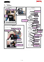
Gear case assembly
6-3-1
Disassembling
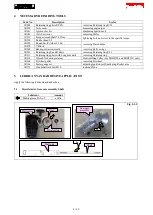
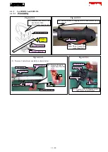
[1] Remove Gear case assembly. (See 6-2-1 Disassembling.)
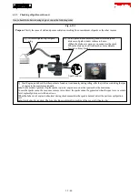
Fig. 6-3-1-1
Fig. 6-3-1-2
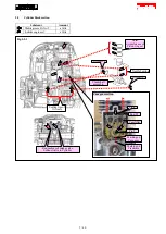
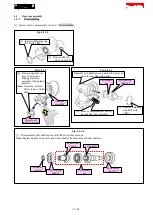
Gear case
assembly
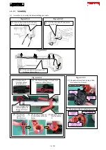
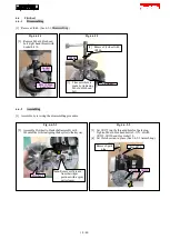
[4] Remove Spiral bevel
gear 14 section by
tapping Gear case
assembly with a plastic
hammer.
Note:
It must be removed
first to remove Cutter
shaft.
Spiral bevel
gear 14 section
Fig. 6-3-1-3
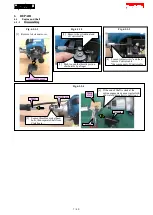
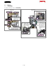
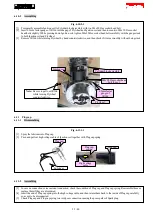
[5] Remove Retaining
ring R-28 with
1R311.
Ball bearing
6001LLU
Cutter shaft
set
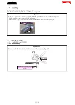
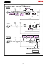
[6] Remove Cutter shaft section by
tapping Gear case assembly.
Note:
If Cutter shaft section is hard to be removed,
warm the rear side with a drier.
Fig. 6-3-1-4
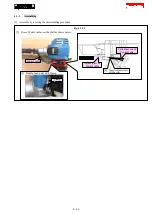
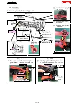
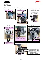
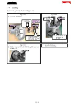
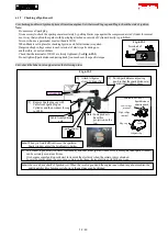
[7] Disassemble Cutter shaft section with 1R269 or Arbor press, etc.
Note:
Replace Spiral bevel gear 14 and Cutter shaft at the same time as Cutter shaft set.
Ball bearing
6001LLU
Retaining
ring S-9
Ball bearing
609ZZ
Cutter shaft
set
Spiral bevel
gear 14
Cutter shaft
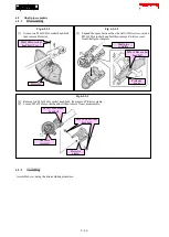
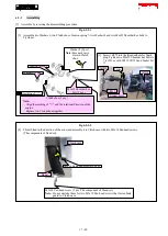
[3] Remove Retaining ring
R-24 with 1R311.
[2] Remove M8x10
+Hex bolt with R.
10 / 40


