13 ENGLISH
Angle setting of the handle
CAUTION:
Always make sure that the handle
is locked in the desired position before operation.
CAUTION:
Do not pull down the lever to
unlock the handle while pulling the switch trigger.
Do not pull the switch trigger while pulling down
the lever and turning the handle.
Failure to do so
may cause a malfunction of the tool.
You can set the angle of the handle to 0°, 45°, or 90°
to the left or right. To change the angle of the handle,
turn the handle while pulling down the lever, and then
release the lever.
►
Fig.3:
1.
Lever
Power switch action
WARNING:
For your safety, this tool is
equipped with lock-off lever which prevents the
tool from unintended starting. NEVER use the tool
if it runs when you simply press the switch lever
and pull the switch trigger without pressing the
lock-off lever. Return the tool to our authorized
service center for proper repairs BEFORE further
usage.
WARNING:
NEVER tape down or defeat pur-
pose and function of lock-off lever.
WARNING:
Before installing the battery car-
tridge on the tool, always check to see that the
switch trigger and switch lever actuate properly
and return to the "OFF" position when released.
Operating a tool with a switch that does not actuate
properly can lead to loss of control and serious per
-
sonal injury.
CAUTION:
Never put your finger on the
switch when carrying.
The tool may start uninten
-
tionally and cause injury.
NOTICE:
Do not pull the switch trigger hard with-
out pressing the lock-off lever. This can cause
switch breakage.
Press the main power button to turn on the tool. The
power lamp lights up when the tool is turned on. To turn
off the tool, press and hold the main power button. The
power lamp goes off when the tool is turned off.
►
Fig.4:
1.
Power lamp
2.
Main power button
NOTE:
The tool is automatically turned off if the tool is
not operated for a certain period.
To prevent the switch trigger from being accidentally
pulled, a lock-off lever is provided. To start the tool,
depress the lock-off lever, and then press the switch
lever and pull the switch trigger. The tool speed
increases by increasing pressure on the switch trigger.
Release the switch trigger to stop.
►
Fig.5:
1.
Switch lever
2.
Lock-off lever
3.
Switch
trigger
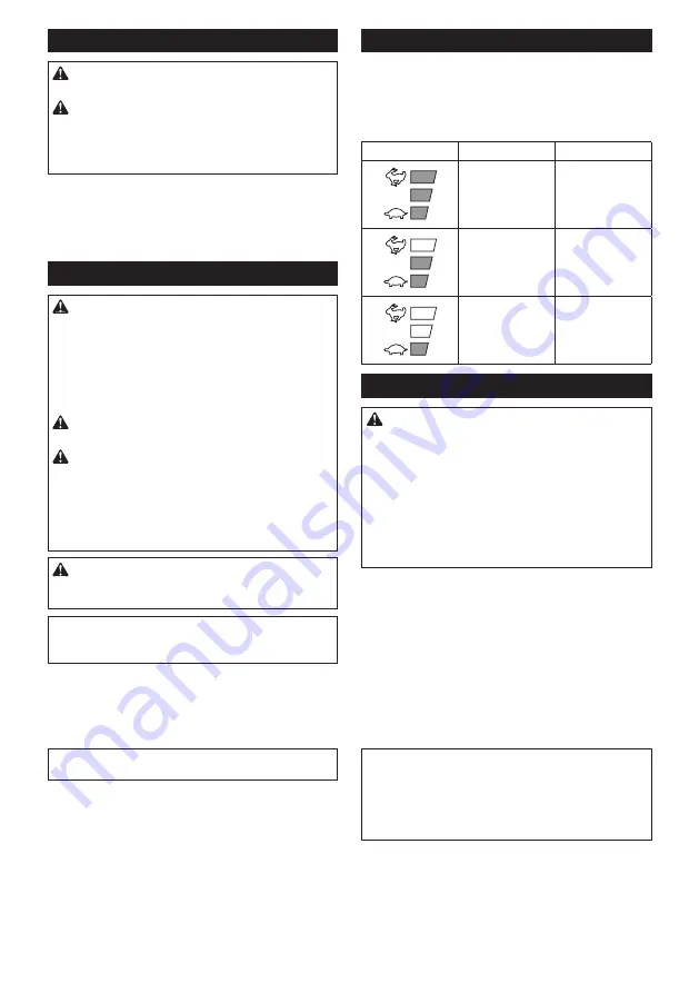
Speed adjusting
You can adjust the tool speed by tapping the main
power button.
Each time you tap the main power button, the level of
speed will change.
►
Fig.6:
1.
Power lamp
2.
Main power button
Indicator
Mode
Stroke speed
High
4,400 min
-1
Medium
3,600 min
-1
Low
2,000 min
-1
Reverse button for debris removal
WARNING:
If the entangled branches or
debris cannot be removed by the reverse func-
tion, switch off the tool and remove the bat
-
tery cartridge, and then remove the entangled
branches or debris using tools such as pliers.
Failure to switch off the tool and remove the bat
-
tery cartridge may result in serious personal injury
from accidental start-up. Removing the entangled
branches or debris by hand may cause an injury,
since the shear blades may move in reaction to
removing them.
This tool has a reverse button to change the direction
of shear blades movement. It is only for removing
branches and debris entangled in the tool.
To reverse the shear blades movement, tap the reverse
button when the shear blades have stopped, then press
the switch lever and pull the switch trigger while press-
ing the lock-off lever. The power lamp starts blinking,
and the shear blades move in reverse direction.
When entangled branches and debris are removed,
the tool returns to the regular movement and the power
lamp stops blinking and lights up.
►
Fig.7:
1.
Reverse button
NOTE:
If the entangled branches or debris cannot be
removed, release and pull the switch trigger until they
are removed.
NOTE:
If you tap the reverse button while the shear
blades are still moving, the tool comes to stop and to
be ready for reverse movement.
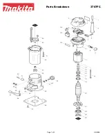
Summary of Contents for DUH502
Page 2: ...2 1 2 3 Fig 1 1 2 Fig 2 1 Fig 3 2 1 Fig 4 1 2 3 Fig 5 2 1 Fig 6 1 Fig 7 1 Fig 8 ...
Page 3: ...3 1 2 Fig 9 1 Fig 10 1 4 2 3 Fig 11 1 2 Fig 12 1 1 Fig 13 1 Fig 14 ...
Page 4: ...4 1 2 3 4 Fig 15 1 2 Fig 16 1 2 Fig 17 1 2 Fig 18 2 1 Fig 19 1 1 2 Fig 20 1 Fig 21 ...
Page 5: ...5 1 Fig 22 1 Fig 23 1 Fig 24 1 Fig 25 1 Fig 26 1 Fig 27 1 2 Fig 28 Fig 29 ...
Page 6: ...6 Fig 30 Fig 31 Fig 32 Fig 33 Fig 34 Fig 35 Fig 36 1 Fig 37 ...
Page 7: ...7 Fig 38 1 2 Fig 39 1 2 Fig 40 1 Fig 41 1 2 Fig 42 2 1 Fig 43 ...
Page 106: ...106 ...
Page 107: ...107 ...


