Makita DTDA040 Series Instruction Manual Download Page 9

9 ENGLISH

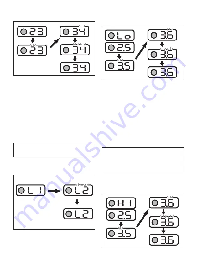
Changing the torque level

When changing the torque level from 23 to 34

1. 

Press the setting button several times until the 

indicator shows 2-digit number which stands for 

the current setting of the torque level.

2. 

Press and hold the setting button until the number 

in the tens place starts blinking.

3.  Set the number in the tens place by pressing the 

setting button briefly. Every time you press the 

setting button, the indicator shows the number 

from "0" to "4" and "F" in a cycle.

4. 

Press and hold the setting button until the number 

in the ones place starts blinking.

5.  Set the number in the ones place by pressing the 

setting button briefly. Every time you press the 

setting button, the indicator shows the number 

from "0" to "9" and "F" in a cycle.

6.  Press and hold the setting button for a few seconds.

NOTE:

 If you are not sure which torque level is suitable for 

your work, set "FF" so that the tool operates in the Free mode.

NOTE:

 If you input "00", "FF" is displayed instead of "00".

Changing the rundown level

When changing the rundown level from L1 to L2

1.  Press the setting button several times until the indicator 

shows 2 characters beginning with "L" followed by a number. 

This stands for the current setting of the rundown level.

2. 

Press and hold the setting button until the indica-

tor starts blinking.

3.  Set the rundown level. Every time you press the setting 

button, the indicator shows from "L1" to "L7" in a cycle. 

The lowest rundown level is "L1" and "L7" is the highest.

4.  Press and hold the setting button for a few seconds.

Changing the shortest workable time range

When changing the shortest workable time range 

from 2.5 to 3.6

1.  Press the setting button several times until the indicator 

shows "Lo" and number alternatively. This stands for the 

current setting of the shortest workable time range.

2. 

Press and hold the setting button until the number 

in the ones place starts blinking.

3.  Set the number in the ones place by pressing the 

setting button briefly. Every time you press the 

setting button, the indicator shows the number 

from "0" to "9" in a cycle.

4. 

Press and hold the setting button until the number 

in the decimal place starts blinking.

5.  Set the number in the decimal place by pressing 

the setting button briefly. Every time you press the 

setting button, the indicator shows the number 

from "0" to "9" in a cycle.

6.  Press and hold the setting button for a few seconds.

NOTE:

 When you set the value smaller than "0.1" for 

the shortest workable time range, the indicator shows 

"-.-" and the shortest workable time range becomes 

disabled. To input "-.-", set the value to "0.9", and then 

press the setting button when the number in the ones 

place is blinking.

Changing the longest workable time range

When changing the longest workable time range 

from 2.5 to 3.6

1. 

Press the setting button several times until the 

indicator shows "HI" and number alternatively. 

This stands for the current setting of the longest 

workable time range.

Summary of Contents for DTDA040 Series

Page 1: ...INSTRUCTION MANUAL Cordless Impact Driver DTDA040 DTDA070 DTDA100 DTDA140 ENGLISH Original instructions Read before use...

Page 2: ...or fire Symbols The followings show the symbols used for the equip ment Be sure that you understand their meaning before use Read instruction manual Ni MH Li ion Only for EU countries Do not dispose o...

Page 3: ...Read all safety warnings instruc tions illustrations and specifications provided with this power tool Failure to follow all instructions listed below may result in electric shock fire and or serious...

Page 4: ...wer tools out of the reach of chil dren and do not allow persons unfamiliar with the power tool or these instructions to operate the power tool Power tools are dangerous in the hands of untrained user...

Page 5: ...ry cartridge 1 Do not touch the terminals with any con ductive material 2 Avoid storing battery cartridge in a con tainer with other metal objects such as nails coins etc 3 Do not expose battery cartr...

Page 6: ...he ambient temperature the indication may differ slightly from the actual capacity When charging When the charging begins the first far left indicating lamp begins to blink Then as charging proceeds t...

Page 7: ...ways set the reversing switch lever to the neutral position 1 B A 1 Reversing switch lever This tool has a reversing switch to change the direction of rotation Depress the reversing switch lever from...

Page 8: ...settings on the tool is not available When you press the setting button the values set on the tool are displayed in order The current setting number is displayed on the indicator Every time you press...

Page 9: ...ting button the indicator shows from L1 to L7 in a cycle The lowest rundown level is L1 and L7 is the highest 4 Press and hold the setting button for a few seconds Changing the shortest workable time...

Page 10: ...ve configured the torque level operate the tool until it stops in the Tightening Auto Stop mode If you have not configured the torque level Free mode operate the tool as necessary 4 Check the measured...

Page 11: ...otection The tool was over loaded and stopped Blinks in red and green alternatively A series of long beeps Remove the cause of overload and then restart the tool Ask your local Makita Service Center f...

Page 12: ...battery cartridge is installed The tool performs the operation test for the LED indicator green red light and beeper The LED indicator lights up in green and then red After that the light turns on fo...

Page 13: ...ool on to start operation NOTICE If you use a spare battery to continue the operation rest the tool at least 15 min NOTICE Use the proper bit for the head of the screw bolt that you wish to use NOTICE...

Page 14: ...circumstances of the fasteners materials and fastening method Perform a test drive before actual work 816 612 408 204 80 918 90 0 5 10 15 20 25 30 35 40 714 70 510 50 306 30 102 M6 M6 M6 DTDA040 DTDA...

Page 15: ...ts OPTIONAL ACCESSORIES CAUTION These accessories or attachments are recommended for use with your Makita tool specified in this manual The use of any other accessories or attachments might present a...

Page 16: ...www makita com Makita Europe N V Makita Corporation 3 11 8 Sumiyoshi cho Anjo Aichi 446 8502 Japan Jan Baptist Vinkstraat 2 3070 Kortenberg Belgium 885712 220 EN 20190625...

Reviews: