8 ENGLISH
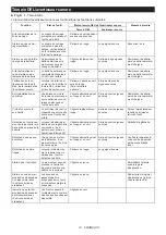
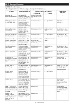
Function
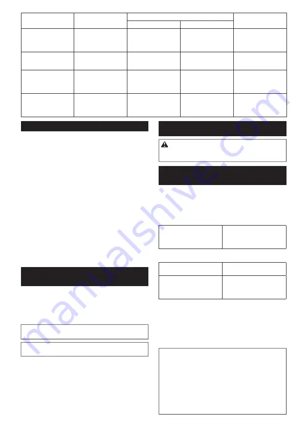
Status of the tool
Status of the LED indicator/beeper
Action to be taken
LED indicator
Beeper
D ouble-h itting d etec tion
W h en th e operator starts
to re-f asten an alread y -f as-
tened sc rew , th e tool
d etec t it and stops.
L igh ts up in red .
A long beep
–
Maintenanc e alarm
A maintenanc e time h as c ome
ac c ord ing to y our preset
number of sc rew s d riv en.
F lic kers in y ellow .
–
R eset th e alarm w ith th e
applic ation sof tw are.
A larm f or unav ailable
d ata c ommunic ation
( w ith th e tool in c onnec -
tion w ith P C )
D ata c annot be
ex c h anged betw een th e
tool and P C in spite of
th e c onnec tion.
F lic kers in y ellow .
–
R estart th e applic ation
sof tw are and re-c onnec t
th e U S B c able.
I nd ic ation th at d ata c om-
munic ation is av ailable
( w ith th e tool in c onnec -
tion w ith P C )
T h e tool is c onnec ted to
P C and d ata c ommuni-
c ation is av ailable.
F lic kers in green.
–
–
Adjusting the fastening torque
W h en y ou w ish to d riv e mac h ine sc rew s, h ex bolts,
etc . w ith th e pred etermined torq ue, ad j ust th e f astening
torq ue as f ollow s.
1.
O pen th e c h ange plate by h and so th at y ou c an
see a h ole.
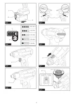
Fig.7:
1.
C h ange plate
2.
P ull th e sw itc h trigger and release it so th at th e
ad j ust ring rotates and th e h ole bec omes v isible. A nd
th en remov e th e battery c artrid ge.
3.
U se an optional ad j ust grip to ad j ust th e f astening
torq ue. I nsert th e pin of th e ad j ust grip into th e h ole
in th e f ront of th e tool. A nd th en, turn th e ad j ust grip
c loc kw ise to set a greater f astening torq ue, and c oun-
terc loc kw ise to set a smaller f astening torq ue.
Fig.8:
1.
A d j ust grip
2.
H ole f or ad j ust grip
4.
I nsert th e battery c artrid ge and be sure th at a
f astening torq ue h as been set up by using a f astening
torq ue tester.
5.
C lose th e c h ange plate by h and sec urely .
Adjusting no-load speed and
revolution angle etc.
Y ou c an ad j ust th e no-load speed , number of turn, etc .
of th e tool w ith y our c omputer. I nstall th e applic ation
sof tw are in y our c omputer and c onnec t it to th e tool w ith
an U S B c able.
Fig.9:
1.
U S B port
2.
U S B c ov er
3.
U S B c able
NOTICE:
Make sure th at th e U S B c ov er c losed
w h en f astening.
NOTE:
F or th e applic ation sof tw are, please c ontac t
Makita sales representativ e.
ASSEMBLY
CAUTION:
Always be sure that the tool is
switched off and the battery cartridge is removed
before carrying out any work on the tool.
Installing or removing driver bit/
socket bit
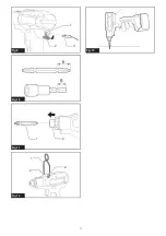
Fig.10
U se only d riv er bit/ soc ket bit th at h as inserting portion
shown in the figure. Do not use any other driver bit/
soc ket bit.
For tool with shallow driver bit hole
A = 1 2mm
B= 9 mm
U se only th ese ty pe of d riv er
bit. F ollow th e proc ed ure
1 . ( Note) Bit-piec e is not
nec essary .
For tool with deep driver bit hole
A = 1 7mm
B= 1 4 mm
T o install th ese ty pes of d riv er
bits, f ollow th e proc ed ure 1 .
A = 1 2mm
B= 9 mm
T o install th ese ty pes of d riv er
bits, f ollow th e proc ed ure 2.
( Note) Bit-piec e is nec essary
f or installing th e bit.
Fig.11:
1.
D riv er bit
2.
S leev e
T o install th e d riv er bit, pull th e sleev e in th e d irec tion of
th e arrow and insert th e d riv er bit into th e sleev e as f ar
as it w ill go.
T h en release th e sleev e to sec ure th e d riv er bit.
T o remov e th e d riv er bit, pull th e sleev e in th e d irec tion
of th e arrow and pull th e d riv er bit out.
NOTE:
I f th e d riv er bit is not inserted d eep enough
into th e sleev e, th e sleev e w ill not return to its original
position and th e d riv er bit w ill not be sec ured . I n th is
c ase, try re-inserting th e bit ac c ord ing to th e instruc -
tions abov e.
NOTE:
When it is difficult to insert the driver bit, pull
th e sleev e and insert it into th e sleev e as f ar as it w ill
go.
NOTE:
A f ter inserting th e d riv er bit, make sure th at it
is firmly secured. If it comes out, do not use it.
Summary of Contents for DFT023F
Page 3: ...1 2 3 Fig 9 Fig 10 1 2 Fig 11 1 2 2 Fig 12 Fig 13 3 ...
Page 71: ...71 ...


