
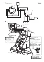

C
ircuit diagram
W
iring diagram
P 4 / 4
Terminal
Speed Change
Switch
Switch
FET
Bruch Holder
Brush Holder
M2
M1
Red
Black
White
Black
Black
Orange
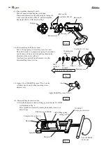
Brush holder lead wire
(Black)
Brush holder lead wire
(Red)
Speed change switch
Lead wire of speed change
switch (white) must not be
loosen in this area.
Fix lead wire of speed change
switch (white) with lead holder.
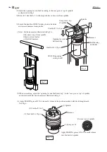
Lead wires of speed change
switch (black and white)
must not be loosen in this area.
Fix the following lead wires
with lead holder.
1 Switch lead wire (Orange) to be
connected to terminal
2 Switch lead wire (Black) to be
connected to terminal
3 Lead wires of speed change switch
(Black and White)
The above lead wires have to be fixed
with lead holder as illustrated in the
following Fig.
Switch side
Terminal side
1
2
3
Lead
holder
Terminal


