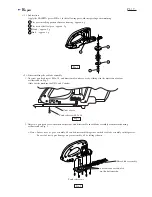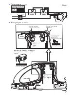
C
ircuit diagram
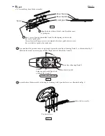
W
iring diagram
P 7 / 7
( for 220V - 240V )
Field lead wires
*White
*Black
*Yellow
Pass lead wires between
pin and wall.
Press lead wires into
the bottom of lea holder.
Place here choke coil with
black and purple lead wires.
Pin
Pass lead wires toward
bottom of housing L,
when receptacle is
connected to brush assembly.
Bottom of housing L
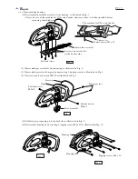
( for 220V - 240V )
Switch A
Color index of lead wires
Black
White
Orange
Yellow
Purple
NC
NO
COM
Switch B
Noise suppressor
NC
NO
COM
Switch A
Choke coil
Choke coil
Insulated terminal
Switch A
Choke coil with black
and orange lead wires.
Switch B
Noise suppressor
Insulated terminal
Press choke coil
with orange
and black lead wires
into bottom.
Terminal block
Press lead wires
into bottom of
lead holder.
Bottom of housing L
Route lead wires toward bottom of housing L,
when receptacles are connected to switches
A and B.
Terminal block
Receptacles


