background image

9

ASSEMBLY

CAUTION:

Always be sure that the tool is switched off and
unplugged before carrying out any work on the tool.

Replacing planer blades

CAUTION:

Handle the blades very carefully when removing or
installing the blades to prevent cuts or injury from the
blades and to prevent damage to the blades. They are
razor-sharp.

Clean out all chips, dust, pitch or foreign matter adhering
to the drum or blades before installing the blades.

Use blades of the same dimensions and weight , or
drum oscillation/vibration will result, causing poor cutting
action and eventually, tool breakdown.

Replace both blades at the same time.

The disposable-type blade has a cutting edge on both
sides. When one cutting edge becomes dull, you can
use the other cutting edge. Always remove resin and dirt
sticking to the reverse side of the blade before using the
other cutting edge. This blade must not be re-
sharpened. When both cutting edges become dull, the
blade should be carefully thrown away.

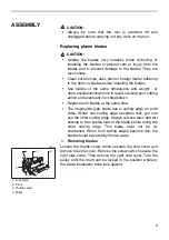
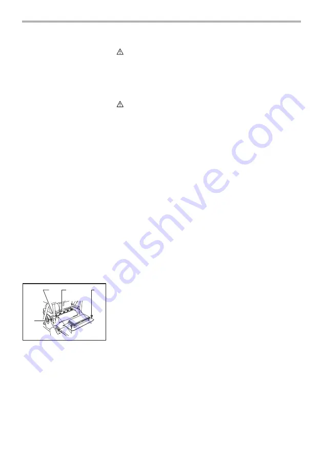
1. Removing blades

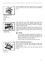
Loosen the thumb screw which secures the chip cover and
remove the chip cover. Remove the screws which secure the
right side cover. Then remove the right side cover. Turn the
pulley until the drum can be locked in the position whereby
the blade installation bolts face upward.

1. Lock plate

2. Drum

3. Thumb screw

4. Pulley

4

1

2

3

003715

Summary of Contents for 2012NB/2

Page 1: ... C T I O N M A N U A L WARNING For your personal safety READ and UNDERSTAND before using SAVE THESE INSTRUCTIONS FOR FUTURE REFERENCE w w w m a k i t a t o o l s c o m Planer MODEL 2012NB 003706 DOUBLE INSULATION ...

Page 2: ...d from tool before turning it on 4 KEEP WORK AREA CLEAN Cluttered areas and benches invite accidents 5 DON T USE IN DANGEROUS ENVIRON MENT Don t use power tools in damp or wet locations or expose them to rain Keep work area well lighted Don t use tool in presence of flammable liquids or gases 6 KEEP CHILDREN AWAY All visitors should be kept safe distance from work area Model 2012NB Cutting width 3...

Page 3: ...ury could occur if the tool is tipped or if the cutting tool is unintentionally contacted 19 CHECK DAMAGED PARTS Before further use of the tool a guard or other part that is damaged should be carefully checked to determine that it will operate properly and perform its intended function check for alignment of moving parts binding of moving parts breakage of parts mount ing and any other conditions ...

Page 4: ...l covers are installed in place before operation 3 Handle the blades very carefully 4 Check the blades carefully for cracks or damage before operation Replace cracked or damaged blades immediately 5 Tighten the planer blade installation bolts securely 6 Remove nails and clean the workpiece before cutting Nail sand or foreign mat ter can cause blade damage 7 Do not wear gloves during operation 8 Do...

Page 5: ...5 SAVE THESE INSTRUCTIONS WARNING MISUSE or failure to follow the safety rules stated in this instruction manual may cause serious personal injury ...

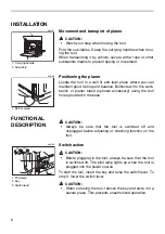
Page 6: ...he bolt holes provided in the base FUNCTIONAL DESCRIPTION CAUTION Always be sure that the tool is switched off and unplugged before adjusting or checking function on the tool Switch action CAUTION Before plugging in the tool always be sure that the tool is switched off The pilot lamp lights up when the tool is plugged into the power source To start the tool insert the key and raise the switch leve...

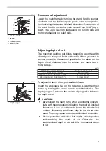
Page 7: ...workpiece flat on the table top Lower the main frame by turning the crank handle counterclockwise The depth gauge will rise and the amount of gauge rise indicates the depth of cut CAUTION Always lower the main frame when aligning the indicator plate with the graduation indicating the desired finished dimension If you raise the main frame into the desired finished dimension additional play in the s...

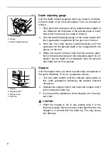
Page 8: ...oned in the Adjusting depth of cut section set the depth of cut shallower than the amount and make two or more passes Stopper Use the stopper when you need to plane many workpieces to the same thickness To do so proceed as follows 1 Turn the crank handle until the indicator plate points to the scale graduation indicating the desired finished dimension 2 Depress the stopper button and lower the sto...

Page 9: ...ually tool breakdown Replace both blades at the same time The disposable type blade has a cutting edge on both sides When one cutting edge becomes dull you can use the other cutting edge Always remove resin and dirt sticking to the reverse side of the blade before using the other cutting edge This blade must not be re sharpened When both cutting edges become dull the blade should be carefully thro...

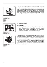
Page 10: ...t wrench may cause overtightening or insufficient tightening of the bolts resulting in severe injury Provide a flat wood block approximately 300 mm 11 13 16 long and 100 mm 3 15 16 wide Place the blade and the set plate on the wood block so that the blade locating lug of the set plate rests in the groove of the blade Adjust the set plate so that both ends of the blade protrude approximately 1 mm 3...
Page 11: ...over and the side cover CAUTION Do not tighten the blade installation bolts without the blade locating lug of the set plate correctly resting in the groove of the blade This may cause damage to the blade and potential injury to the operator Do not turn the tool on with the chip cover removed Hood set optional accessory When you wish to maintain clean operations through easy dust collection connect...

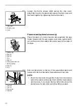
Page 12: ...legs Now set the planer on the top of the assembled stand and secure with the four hex bolts flat washers and hex nuts NOTE Insert the hex bolts through the holes from the reverse side of the stand and secure them with the flat washers and hex nuts If you insert the hex bolts from above the planer base the hex bolts cannot be firmly secured 1 Chip cover 2 Thumb screw 3 Hood 1 2 3 003723 1 Rubber c...

Page 13: ...itch on the tool and wait until the blades attain full speed The workpiece should not be in contact with the feed roller when you turn the tool on Then insert the workpiece flush with the table top When cutting a long or heavy workpiece lift up its end slightly at the start and the end of the cut to avoid gouging or snipping at the extreme ends of the workpiece The use of the tool top enables quic...

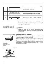
Page 14: ... and also place a ruler on the postcard Turn the adjusting screw with the hex wrench until the end of the sub table contacts the ruler Now the end of the sub table is from 0 1 mm to 0 3 mm 0 004 0 012 above the table surface 1 2 3 Less than 130 mm 5 1 8 long Having a groove more than 130mm 5 1 8 wide Having grooves at intervals of 130 mm 5 1 8 wide 3 Less than 130 mm 5 1 8 long Having a groove mor...

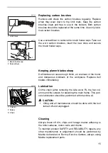
Page 15: ...the workpiece Replace dull blades immediately Lubrication Oil the chain after removing the side cover R the four col umns and the screws for elevating the main frame This peri odic lubrication should be performed with machine oil CAUTION Oiling and all maintenance should be done with the tool turned off and unplugged Cleaning Always brush off dirt chips and foreign matter adhering to the roller su...

Page 16: ...he use of any other accessories or attachments might present a risk of injury to persons Only use accessory or attachment for its stated purpose If you need any assistance for more details regarding these accessories ask your local Makita service center Planer blade Planer stand Magnetic holder Socket wrench Hex wrench Hood set ...

Page 17: ...17 First Class Postage Required Post Office will not deliver without proper postage Makita U S A Inc 14930 Northam Street La Mirada CA 90638 5753 Fold Cut ...

Page 18: ...ability Power Other Design Features Size Price Makita Brand 5 Any comments MAIL THIS PORTION Your answers to the following questions are appreciated BE SURE TO COMPLETE THE CUSTOMER S PORTION OF THIS FORM AND RETAIN FOR YOUR RECORDS DATE PURCHASED MODEL NO SERIAL NO INTL LAST NAME COMPANY NAME STREET ADRESS CITY STATE AGE ZIP CODE PHONE AREA CODE STATUS Married SEX M F Single MONTH DAY YEAR Under ...

Page 19: ... St Louis MO 63126 2221 314 909 9889 NEBRASKA 4129 S 84th St Omaha NE 68127 402 597 2925 NEVADA 3375 S Decatur Blvd Suites 22 24 Las Vegas NV 89102 702 368 4277 NEW JERSEY 251 Herrod Blvd Dayton NJ 08810 1539 609 655 1212 NEW YORK 4917 Genessee Street Cheektowaga NY 14225 716 685 9503 OREGON 828 19th Avenue N W Portland OR 97209 503 222 1823 PENNSYLVANIA 1704 Babcock Blvd Pittsburgh PA 15209 412 8...

Page 20: ...zed Service Centers If inspection shows the trouble is caused by defective workmanship or material Makita will repair or at our option replace without charge This Warranty does not apply where repairs have been made or attempted by others repairs are required because of normal wear and tear the tool has been abused misused or improperly maintained alterations have been made to the tool IN NO EVENT...

Reviews: