


Panel Controls:
The knobs on any particular module are utilized to set values for their respective parameters. Often a
value can be altered by
Control Voltage
(
CV
) in an input jack, which can be visualized as an invisible
hand “turning” the knob. We will go into much more detail about CV, which is in many ways the
defining characteristic of the modular synthesizer.
The medium (white) knobs and large (grey) knobs are generally used for setting base values, while
small (white) knobs are used to
Attenuate
(i.e. “scale”) and/or
Invert
incoming CV.
30
(CONT'd)
This section contains short descriptions and examples for all the connections
that are not part of the gold wire signal flow of the 0-Coast. Connecting cables
to these patch points has the potential to expand the capabilities of the
0-Coast, without changing anything about its default operation. In the next
section we will discuss patch points that override normalizations and have the
capability to change the entire voice structure of the 0-Coast.
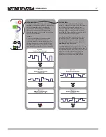
CTRL
TEMPO INput:
This input looks for a series of Gates, Clocks, and anything else
with a hard edge. These clocks are combined with [TAPPING] of PGM_B and/or
MIDI Clock, if Enabled.
CLocK OUTput:
A regular series of gates is output from this jack, the tempo of
which is set by sending pulses to the TEMPO jack, tapping the PGM_B button
at the desired tempo, or MIDI CLocK (
Page 34
for information about MIDI
options). CLocK could be patched to, for example, the TRIGger input on SLOPE,
to create a time-synced series of functions.
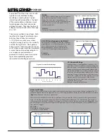
Stepped Random Voltage OUTput
A new random voltage is output from this
jack with each cycle of the CLocK (See
Figure 63
). Patch to 1v/Oct with
DYNAMICS held open to hear its effects on oscillator pitch.
Voltage MATH: See Page 33
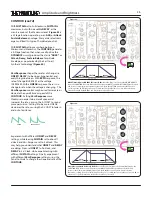
Oscillator:
Triangle OUTput:
This output is the core of the Oscillator, has few overtones
and is a classic building block for West-Coast synthesis. The output is
hardwired to the input of the OVERTONE section, and also normaled to the
FUNDamental portion of the BALANCE control. Patching from this output
does not remove it from BALANCE (to do that, patch a cable into the BALANCE
input), but allows it to be patched elsewhere at the same time. For example,
patch it to MULTIPLY to hear the wave multiplier modulated very fast, at the
rate of the Oscillator.
Square OUTput:
This output is also derived from the Oscillator core. It has
the same set of overtones as the Triangle, but the overtones appear at much
greater amplitudes, which makes it a classic building block for subtractive
(East-Coast) synthesis. Patch it to the Balance Signal INput and set balance Full
CCQ to hear it.
Lin FM INput:
The typical use for Frequency Modulation is to super-impose
the frequency of one oscillator upon another. The result is that the oscillator
that is FM'd will carry the modulating oscillator's pitch information in the form
of harmonics. Linear FM attempts to preserve the base frequency of the
carrier oscillator, allowing for harmonically rich waveforms to be generated
while still being able to track the musical scale properly. The Linear FM input is
AC coupled and has a Level control. The 0-Coast has only one Oscillator, but
when SLOPE is set to CYCLE it can oscillate at audio-rate, becoming a great FM
source. Patch SLOPE to LinFM to hear this. Try starting with Rise and Fall at
about 9:00, and Response set to Linear. As you increase the FM Index (using
the LinFM input attenuator), the Amplitude of the signal Frequency
Modulating the 0-Coast oscillator is increased and the resulting signals the
Triangle, Square, Dynamic, and Line OUTputs will become increasingly more
complex. At greater than 80% Level, the Linear FM bus goes into overdrive
and the 0-Coast will not track accurately. For extreme (exponential) FM, try
patching SLOPE directly to the 1V/Oct input instead,
Figure 33
.
Frequency Modulation (FM):
Frequency Modulation
is exactly what the name
seems to describe: modulating the frequency, such
as that of an oscillator, using a control voltage.
Technically, any such control is FM (patching a
sequence to the 1V/Oct Input, for example).
However, the phrase
FM Synthesis
usually refers to
audio-rate FM
, in other words using at least one
audio-rate oscillator to modulate the frequency of
another. This practice results not in a melodic
sequence of pitches, but rather in a change in
timbre
.
More on FM:
The 0-Coast is laid out to make FM very fast to
perform. There is a CV input labeled "
LIN.
"
Any
signal patched modulates the VCO's frequency at a
Depth set by the associated input Attenuator. For
example, with SLOPE <Cycling>, patch SLOPE
OUTput to the
Linear FM
input, causing the ear to
hear the modulation as a difference in Timbre, rather
than a Continuous Modulation of pitch,
Figure 64
.
As the Attenuator is turned up, the Depth of
Modulation gets higher and the timbral shift
becomes more pronounced. At maximum, it is
slightly overdriven which can actually start to warp
the perceived pitch of the oscillator.
Figure 64:
Oscillator Linear FM
+5V
-5V
Time
Figure 63:
Random Stepped Voltage
+10V
0V
0
1
2
3
4
5
6
7
8
9
Number of Clock Pulses


