Major MR150 Operator'S Manual And Parts List Download Page 18


14 


Using the Mower 

Before working always check that all the safety shields listed in  page 6 are installed, correctly mounted and 
efficient.  Failing this, stop the mower and replace or repair the damaged shields.  Never continue work until all 
the shields installed by the manufacturer are efficient. Contact your nearest after-sales service centre if 
necessary.  Always become familiar with mower use before working with the implement. Make sure that you 
know how to quickly stop the work operations.  
 
Step 1:  Lower the machine until the four wheels are resting on the ground. 
 
Step 2:  If any further adjustments are necessary, carry out the work as described in the paragraph – Adjusting 
the Cutting Height 
 
Step 3: Accelerate the tractor by depressing the accelerator pedal to about half its travel and then engage the 
PTO.  
 
Step 4:  Advance with the tractor, setting the  PTO to the required rpm rate (usually 540 or 1000 rpm). The 
travelling speed of the tractor must be selected according to the grass to be cut, its quantity and the cutting finish 
required. Optimum work speeds will be between 3 and 8 Km/hour (2/5 mph).  


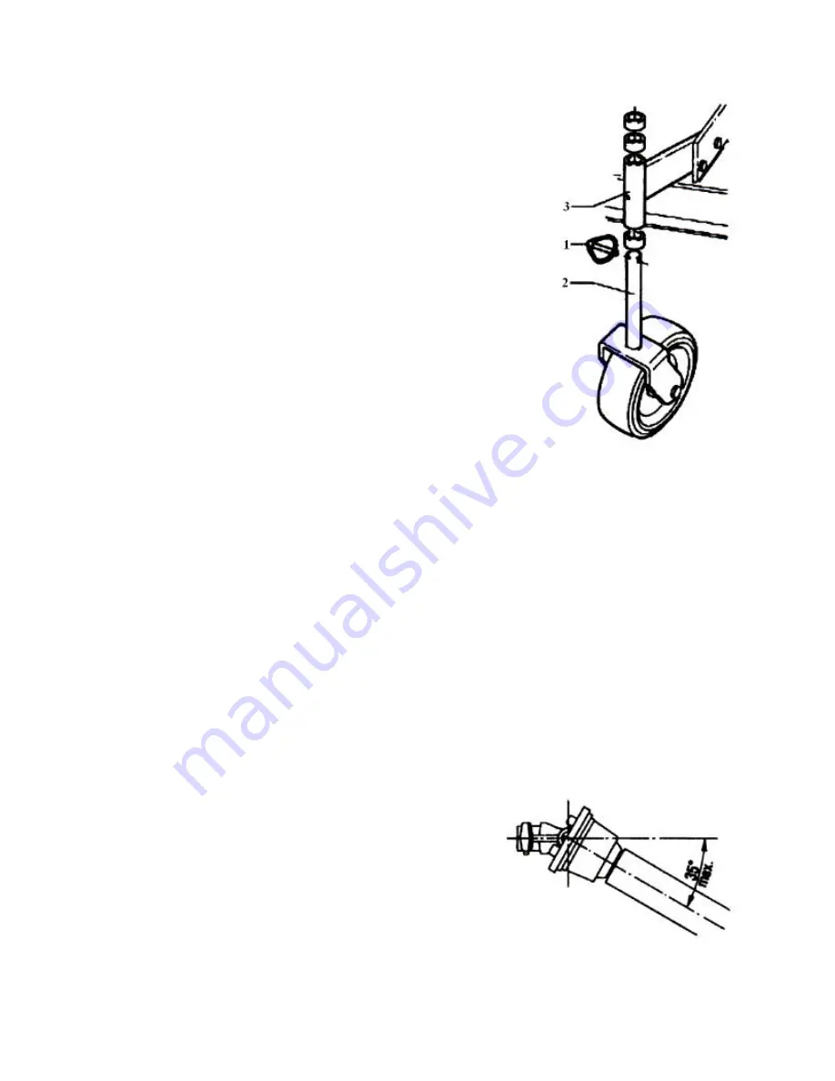
Adjusting the Cutting Height – Fig 6.1 

To alter the cutting height, proceed as follows: 


Remove the split pin 1 


Slide out the wheel axle 2; 


Slide the spacers supplied with each wheel or parts of these 
spacers onto the wheel axis 2 according to the height 
required. 


Mount the wheel axis 2 onto the wheel support 3, slide any 
remaining spacers on and lock them in place with the split 
pins 1 (see fig. 6.1).  The spacers are all different-sized to 
enable the height to be altered as   accurately as possible.  
The more spacers are placed below the wheel support "3", 
the further away the blades will be from the ground (until 
reaching the maximum cutting height). 


IMPORTANT:  

However the spacers are laid out, the wheel axle must 

have the minimum clearance. 
 

CAUTION:  

Always check that the driveline is unable to touch the 

implement when the mower is raised from the ground. 


Important:   


The cutting finish will better if  the tractor travels slowly while 
operating. Always raise the implement from the ground during 
manoeuvres, round bends and when reversing. After having 
worked for a few meters, stop and check whether the desired 
result is being obtained. Make any adjustments as may be 
necessary and then continue with the job. 


Never reverse with the implement unless this is strictly 
necessary.  In such cases, disengage the pto and carefully 
check to see whether there are any obstructions at the rear. 


Never lift the implement more than 250 mm from the ground with the pto engaged or the driveline 
could break and risk injury to the operator. The maximum tilt the driveline can bear with the  PTO 
engaged is 35° (

Fig. 6.2)


Fig. 6.1 

Fig. 6.2 

Summary of Contents for MR150

Page 1: ...Operator Manual and Parts List MAJOR FINISHING MOWERS MR150 MR180 and MR235...

Page 2: ...___________________________________________ ADDRESS ________________________________________________________ ________________________________________________________ __________________________________...

Page 3: ...7 Hitching to the tractor Preliminary instructions on use of the machine 8 Coupling the machine to the tractor 11 Shortening the driveline 12 Use of the Machine Preparing the implement for work 13 Us...

Page 4: ...ts of THE SUPPLY OF MACHINERY SAFETY REGULATIONS 2008 S I No 299 of 2007 Safety Health and Welfare at Work General Application Regulations 2007 Ireland Health Safety at Work etc Act 1974 c 37 UK EN IS...

Page 5: ...vent of faults or problems which require the assistance of a qualified technician contact the manufacturer directly or your nearest dealer This machine is consigned according to the warranty condition...

Page 6: ...utting height 5 Rear discharge conveyor 6 Side closing part 7 Side discharge conveyor MR150 MR180 only 8 Rear closing part Fig 2 2 Side Discharge Mower The main feature of this machine is its versatil...

Page 7: ...ld be changed before the implement is used Unless it is correctly protected the driveline could even cause the user s death since it can catch on parts of the body or clothing Always check that the sh...

Page 8: ...ing on slopes it is advisable to reduce the work speed gradually varying the speed and direction of the vehicle during manoeuvres Never repeatedly stop and start the machine 6 Never operate on wet sli...

Page 9: ...d use the lowest possible pressure 4 At the end of the job check and inspect the implement while it is still disconnected from the tractor Check the cutting blades for wear Never carry out welding ope...

Page 10: ...eel with the fork slipping off accidentally 4 Driveline shield The driveline is supplied with adequate plastic shields and relative fixing chains 5 Guards only on the rear discharge version Prevents t...

Page 11: ...re parts or those which are not specific to the machine Failure to observe all or some of the instructions exceptional weather conditions DELIVERY OF THE MOWER All mowers are tested in our plants to e...

Page 12: ...he following the assembly of the separate pieces transforming the machine from rear to side discharge versions or vice versa The operator responsible must have the necessary skills and background to c...

Page 13: ...or 7 M12 Nut Auto Lock 16 M10 x 20 Screw UNI 5739 8 M12 x 35 Screw UNI 5739 17 Washer M10 9 M12 Nut Auto Lock Transforming the Rear Discharge Mower into the Side Discharge Version MR150 MR180 only Mou...

Page 14: ...the washers 6 Fig 5 5 Step 1 Unscrew screws 2 and dismount the rearguard 1 unscrew screws 4 to dismount the side guard 3 Fig 5 6 Step 2 Mount the rear conveyor 1 using the screws 2 M10x20UN15739 and...

Page 15: ...if necessary Check that the rotors supports have been greased Consult page 15 for the required type of lubricant Check that the blades are free from foreign bodies Very worn or broken knives must be...

Page 16: ...hown in the diagrams to the right Fig 5 12 Contact your nearest dealer or a specialised retail outlet if the PTO must be replaces with a longer one since this must belong to the same power category an...

Page 17: ...to the mower during either work or transport Preparing the Mower for Work Always be careful to check that the power rating of the tractor used to tow the implement does not exceed the maximum power r...

Page 18: ...supplied with each wheel or parts of these spacers onto the wheel axis 2 according to the height required Mount the wheel axis 2 onto the wheel support 3 slide any remaining spacers on and lock them...

Page 19: ...g operations are carried out If interventions must inevitably be carried out while the machine tool is still attached to the tractor proceed as follows disengage the power takeoff insert the brake tur...

Page 20: ...lt during transport and need topping up Inspections to be made periodically Every 8 hours service Grease the rotary shaft supports see diagram below Check the condition of the driveline and grease the...

Page 21: ...ay between the multiplier pulley and the rotary shaft the belts yield by approximately 12mm 1 2 inch To tighten the belts loosen the nut 1 and turn the screw 2 until the belt is as tight as required W...

Page 22: ...hich is suitable for the task in hand e g goggles gloves and waterproof overalls Lubricant Greasing Points newer models now have grease extensions Fig 7 5 Table of Recommended Lubricants AGIP ESSO IP...

Page 23: ...onsult the weight chart on the front page of this booklet Disposing of the Machine When scrapping the machine the procedure to adopt is as follows remember that it is almost completely made of ferrous...

Page 24: ...00 31 Bracket 4 40234200 40234200 10 Hook 1 30120100 30120100 32 Spacer 4 32174600 32174600 11 Nut 4 62011000 62011000 33 Spacer 4 32174700 32174700 12 Casing 2 39259300 39259400 34 Spacer 4 32174900...

Page 25: ...16600 14 Nut 6 62011100 62011100 4 Screw 12 60021300 60021300 15 Spindle Assembly 45115100 45115100 5 Spacer 3 32174000 32174000 16 Pulley 2 68086700 68086700 6 Support 3 40234100 40234100 17 Belt 2 6...

Page 26: ...31078500 4 Nut 3 62010400 62010400 9 Chain 68086000 68086000 5 Gripping 1 40233300 40233400 10 Complete Kit 45113100 45113200 SIDE DISCHARGE MR150 MR180 Item No Description Qty MR150 Part No MR180 Pa...

Page 27: ...23 GEARBOX MR150 MR180 MR235 Item No Description Qty MR150 Part No MR180 Part No MR235 Part No 1 Complete Gearbox 1 46035200 46035200 46035200...

Page 28: ...1 Screw 3 60021600 60021600 7 Screw 6 60021600 60021600 2 Washer 3 61004900 61004900 8 Gripping 1 40233000 40233100 3 Deflector 1 40233600 40233700 9 Screw 2 60017900 60017900 4 Nut 3 62010400 620104...

Page 29: ...crew 1 60027500 36 Nut 4 62010400 11 Spacer 2 32174700 37 Washer 4 61004900 12 Spacer 1 32187300 38 Plate 1 40279100 13 Wheel 1 68087600 39 Screw 1 60030200 14 Disc 68099100 40 Washer 1 61004900 15 Sp...

Page 30: ...0 67016600 15 Pulley 4 68099300 4 Spacer 5 32187500 16 Pulley 1 68099400 5 Screw 20 60021300 17 Pulley 1 68099500 6 Grease Fitting 5 64001800 18 Belt 2 68092300 7 Nut 20 62010400 19 Pulley 2 68099600...

Page 31: ...Tube 1 68100200 8 Grease Fitting 5 64001800 4 Tube 1 68100300 9 Connection 5 68101200 5 Tube 1 68100400 ANTI SCALPING ROLLER MR235 Item No Description Qty MRP235 Part No Item No Description Qty MRP23...

Page 32: ...le to first pass Grass wet Allow grass to dry before mowing Slow ground speed of tractor but keep engine running at full PTO rpm Cutting lower will help Gearbox overheating Low on lubricant Fill to pr...

Page 33: ...ace blades or bolts in sets Drivelines not phased correctly Implement and tractor yokes must be in line Phase the driveline Replace if necessary Gearbox noisy Worn bearing Replace bearings Low oil in...

Page 34: ...artment at Major to approve or reject a Warranty claim is final and binding NOTE To process a warranty claim it is necessary to quote the Model Serial Number which are printed on the Major Serial Plat...

Page 35: ...allyhaunis Co Mayo Ireland Tel 094 9630572 UK OFFICE Major Equipment Ltd Major Ind Estate Heysham Lancs LA3 3JJ UK Tel 01524 850501 NL GERMANY OFFICE Major Equipment Intl Ltd Postbus 29 NL 7700 AA Ded...

Reviews: