5
6
General Description
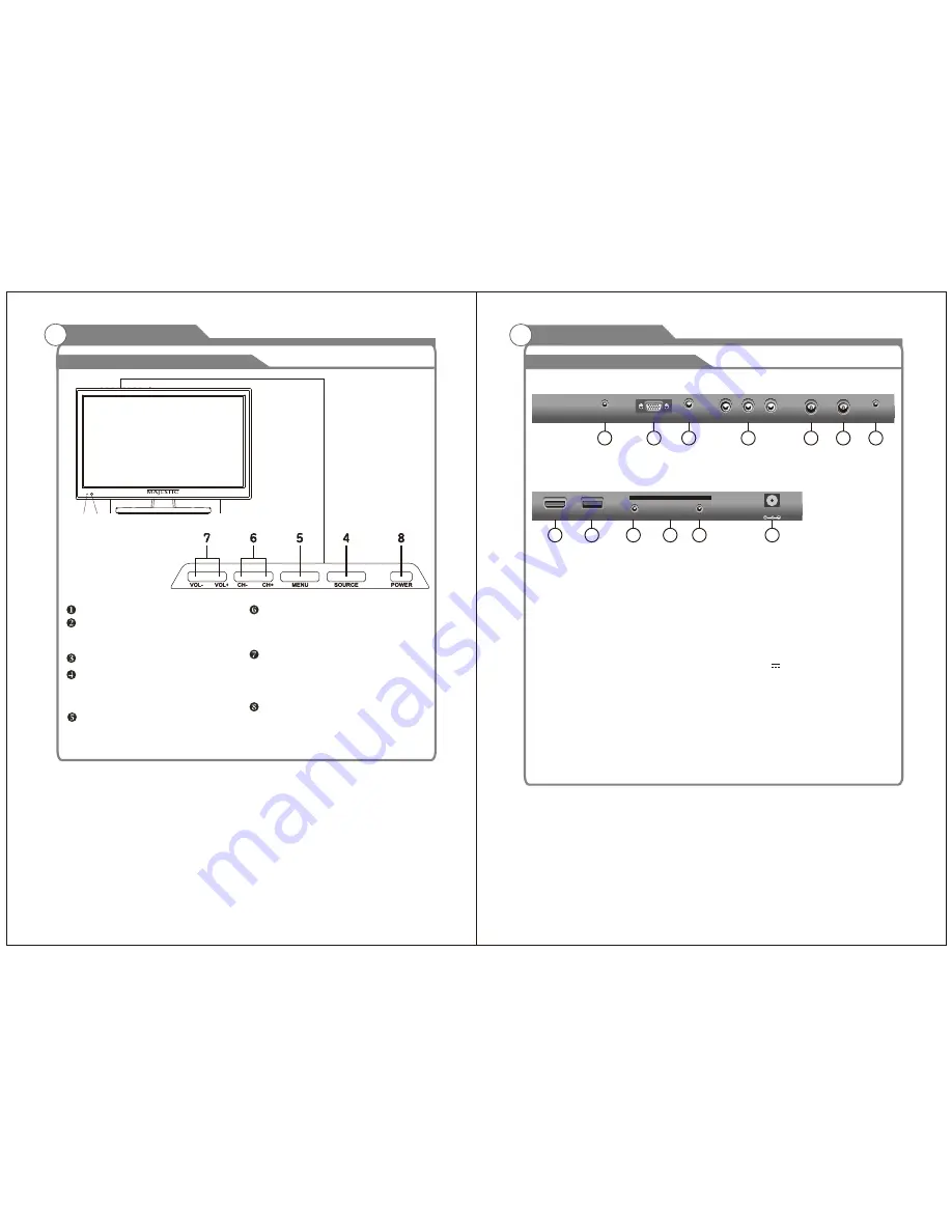
Overview of back panel
Rear Side
Rear Side
1. EARPHONE
Connecting for headphone.
2. VGA
Connected to the VGA output jack on a
personal computer.
3.
PC AUDIO
Connected to the audio output jack on a
Personal computer.
4.
AV Out:
Connect one end of the yellow
Video Cable to the VIDEO jack of AV OUT
connection
.
Connect the other end to the VIDEO IN jack
on the VCR
.
5.
TV1
Connected to external SATELLITE to receive.
6.
TV2
Connected to external antenna to receive
the ATV/DTV program in ATV/DTV mode.
7.
COAXIAL Out
Digital Audio output for Surround Sound
amplifiers and other devices.
8.
HDMI(MMMI)
Connecting for HDMI signal.
MMMI:
Allows you to connect your Android
or iOS phone or Tablet to display the
mobile device on the TV Screen
.
9. USB (5V 500mA)
Connecting for USB device.
.
10 MINI YPbPr
Connecting for the Y/Pb/Pr Input in
Component mode.
11. CI
Used to insert the CI card.
12. MINI AV
Connecting for VIDEO signal input in
Composite mode.
13.
POWER(DC 12V)
input
USB
8
MINI YPbPr
MINI AV
CI
9
10
12
11
HDMI
(MMMI)
POWER IN
DC 12V
VGA
13
PC
AUDIO
IN
TV2
2
3
4
6
7
EARPHONE
OUT
COAXIAL
OUT
VIDEO
R
L
1
General Description
Overview of front and side panel
SPEAKER
REMOTE CONTROL SENSOR
POWER INDICATOR
Green: In power on mode.
Red: In standby mode.
MENU
Press to see an on-screen menu of your
TV's features.
SOURCE
Change and select the desired mode
(Satellite,DTV, ATV,AV, YPbPr)
In the on-screen menu, use the CH +/-
buttons as up/down arrow buttons.
VOL+/-
Press to increase or decrease the volume.
In the on-screen menu, use the VOL +/-
buttons as left/right arrow buttons.
POWER
CH+/-
Press to change channels.
Press this button to turn the TV on or off.
TV1
5
1
2 3
3


