


20
7
_
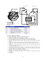
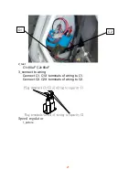
Connect housings of wiring to switch as fellow:
Housing No: PV11 to 11 terminal of switch,
Housing No: PV12 to 12 terminal of switch,
Housing No: PV13 to 13 terminal of switch,
Housing No: PV21 to 21 terminal of switch,
Housing No: PV22 to 22 terminal of switch,
Housing No: PV23 to 23 terminal of switch,
8
_
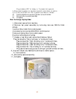
Fix screw SD3.5x13, amount the switch to cabinet.
9
_
Complete.
B: 1level pressure switch:
The process is same as above, wiring connect as fellow:
Housing No: PV11 to 1 terminal of switch,
Housing No: PV12 to 2 terminal of switch,
Housing No: PV13 to 3 terminal of switch,
Housing No: PV14 to 4 terminal of switch,
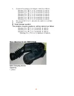
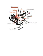
Hose dispenser to tub (9000V\9900)
Micro delaying device
Capacity
1
_
picture
Summary of Contents for MJ-9000V
Page 1: ...1 MJ9000V TECHNICAL MANUAL MJ9900 Installation dimension ...
Page 7: ...7 ...
Page 9: ...9 ...
Page 11: ...11 ...
Page 13: ...13 ...
Page 15: ...15 ...
Page 16: ...16 ...
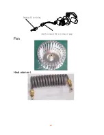
Page 25: ...25 Fan Heat element ...
Page 27: ...27 ...


