MIEN3024/3026 Rack Mount Industrial Ethernet Switch
- 9 -
Figure 2-13 MIEN3024-16S/M (8 100M TX and 16 100M FX ) rear panel
diagram
Figure 2-14 shows the schematic diagram of the rear panel of
MIEN3024-24S/M (24 100M FX).
Figure 2-14 MIEN3026-24S/M (24 100M FX) rear panel schematic diagram
For most industrial applications, 19-inch rack installation is very
convenient. The installation situation of the rack should be checked before
installation. It mainly includes the following two contents:
Sufficient space to install product
suitable power introduction for the work of the product
2.2.3. Cable connection
After correct installation, you can install and connect the cables, mainly
below following interfaces:
Operation port
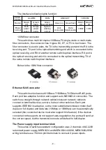
The terminal device interface provided by the industrial Ethernet switch is
a 10Base-T/100Base-TX Ethernet RJ45 interface,use a straight-through
network cable to connect to the terminal device, and a crossover network cable
to connect to the network device.
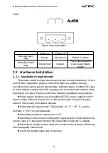
Power connection
The standard of the power on our product label could be connected after
all the other cables are ready.
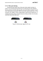
2.2.4. Fiber optic connection
This series of rack-mounted industrial Ethernet switches respectively
provide multiple 100Base-TX single-mode or multi-mode optical fiber
interfaces. The type of optical fiber interface can be selected from SC, FC or
ST.
Attention
:
This switch uses lasers to transmit signals on fiber optic cables. The
laser meets the requirements of Class 1 laser products, and normal
operation is harmless to eyes.However, when the equipment is powered on,
do not look directly at the optical transmission port and the end face of the
optical fiber terminator.

