background image

MIEN2204 Series Unmanaged Industrial Ethernet Switch

- 10 -

The specifications, quantity, routing direction, and location of the cables to

be laid should meet the design requirements of the construction drawing. The
wiring length of each cable should be determined according to the actual
location.The user cables and power cables should be laid separately.

There must be no disconnection or joints in the middle of the laid cables
Cables should be laid out neatly in the aisle, and the bends should be

even, smooth and straight

The cable should be straight in the channel, and should not go out of the

channel and block other wire entry and exit holes. The cable should be bound
and fixed at the location of the cable exit from the channel or the cable bend

When the cables, power cords, and ground wires are laid in the same slot,

the cables, power cords and ground wires cannot be overlapped or mixed.
When the cable is too long, the cable must be neatly placed in the middle of the
cable rack, and cannot be pressed on other cables

When laying pigtails, prevent the optical cable from knotting and minimize

the turning points, and the turning radius should not be too small. The lashing
should be moderately tight and not too tight. When laying on the cable rack, it
should be placed separately from other cables

There should be corresponding marks at both ends of the cable, and the

content of the marks is concise and easy to maintain

Attention

When laying pigtails, prevent the optical cable from kinking and minimize

the turning point, and the turning radius should not be too small. If the turning
radius is too small, it will cause serious loss of the link optical signal. Affect the
quality of communication.

Summary of Contents for MIEN2204 Series

Page 1: ...MIEN2204 Series Unmanaged Industrial Ethernet Switch User Manual Edition V2 0 Wuhan Maiwe Communication Co Ltd...

Page 2: ...tion provided by our company in this manual does not represent for corresponding authorization on these information Our company attempts to ensure the accuracy and applicability for the information pr...

Page 3: ...with each other frequently inspection is needed Please keep the fiber socket and plug clean Do not look directly at the fiber section when the equipment is working Please keep the equipment clean and...

Page 4: ...l Power Supply Design 1 1 2 3 Rugged Design 1 1 3 Packing List 2 2 Interface 3 2 1 Ground Screw 3 2 2 Power Input Interface 3 2 3 LED Indicator 4 2 4 Ethernet Rj45 Port 5 2 5 10 100M Optical Fiber Int...

Page 5: ...ing type is store and forward exchange mode 10Base T 100Base TX self adaptive MDI MDIX Ethernet electrical interface mode supporting full duplex or Half duplex 100Base X optical fiber interface interf...

Page 6: ...of MIEN2204 series products contains the following items If any of the following items are lost or destroyed please contact the agent or the customer service center of Maiwe who will assist you in rep...

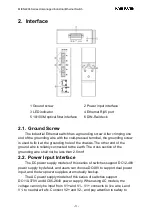
Page 7: ...her end of the ground wire is reliably connected to the earth The cross section of the grounding wire shall not be less than 2 5mm 2 2 Power Input Interface The DC power supply models of this series o...

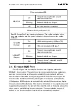
Page 8: ...Please pay attention to the sequence of operations above 2 3 LED Indicator The front panel LED indicators of this series of switches indicate the current working status of the switches Specific instr...

Page 9: ...doesn t establish a valid network connection 2 4 Ethernet Rj45 Port Each RJ45 port has an adaptive function and supports automatic MDI MDI X connection The switch can be connected to terminal equipme...

Page 10: ...iber interfaces need to be used in pairs TX and RX are a pair The TX port is the optical transmitting end which is connected to the optical receiving end RX of the optical interface of another remote...

Page 11: ...lled on DIN rails Check if there are cables and connectors required for installation Attention Be sure to disconnect the power cord before installing or connecting the Ethernet switch Calculate the ma...

Page 12: ...e installation It includes the following two contents Whether the DIN rail is fixed and strong whether other equipment is installed on the DIN rail and whether there is enough space for installing the...

Page 13: ...cal transmission port and the end face of the fiber terminator The steps to connect pluggable fiber optic modules are as follows Remove and keep the rubber sleeve of the SC ST FC port When not in use...

Page 14: ...d When the cables power cords and ground wires are laid in the same slot the cables power cords and ground wires cannot be overlapped or mixed When the cable is too long the cable must be neatly place...

Page 15: ...le Multi mode fiber 100M multi mode 1310nm 2km Single mode fiber 100M single mode 1310nm 20 40km 1550nm 60 80km Front panel LED lights Port light LINK ACT SPEED Power status light PWR Input power DC11...

Page 16: ...ection Standard models 100M rj45 port 100M Fiber SC ST FC port SC ST FC Voltage rage Single mode Single mode fiber Muti mode MIEN2204 2S 2 2 0 0 1 DC power supply DC12 48V DC48V 36 72V 2 AC power supp...

Page 17: ...MAIWE COMMUNICATION CO LTD Add Building 2 Area E Phase ii Optical valley core center No 52 Liufang road East Lake Hi tech Development Zone Wuhan China Phone 027 87170215 16 Fax 86 027 87170217 www mai...

Reviews: