background image

Assembly Instructions 


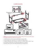
NOTE: Please do not fully tighten all bolts until you finish assembling all parts. Once assembled, go back 
and fully tighten all bolts. This will make the assembly easier. 


1.


Unpack the unit and confirm that you have all the hardware and required parts.  

2.


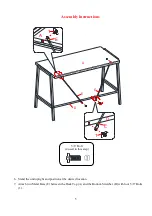
Position the Desk Top (A) upside down on a level and protected surface as shown. 

3.


Attach the Left Side Frame (B) to the Desk Top (A) with two 2 1/4” Bolts (2) and two Washers (3 and 4). 

4.


Attach the Bottom Stretcher (D) to the Left Side Frame (B) with two 5/8” Bolts (1). 

5.


Repeat the same procedure to attach the Right Side Frame (C) at the opposite side. 

B/C

B/C

1

1

D

D

Lock Washer 

(4 used in this step) 


5/8” Bolt 

(4 used in this step)


Flat Washer 

(4 used in this step) 


2 1/4” Bolt 

(4 used in this step)


Summary of Contents for MS18-D2-1011-01

Page 1: ...parts are missing DO NOT return this item to the store where it was purchased Please call our customer service number and have your instructions and parts list ready to provide the model name part na...

Page 2: ...eep all hardware part out of reach of children 4 Please wait until all steps are completed before tightening bolts 5 Make sure all bolts are tightly fastened before the unit is used MAXIMUM LOAD 200 l...

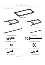
Page 3: ...present before beginning assembly A Desk Top Qty 1 B Left Side Frame Qty 1 C Right Side Frame Qty 1 D Bottom Stretcher Qty 1 E Metal Bar Qty 2 1 5 8 Bolt Qty 8 1 extra 2 2 1 4 Bolt Qty 4 1 extra 3 Lo...

Page 4: ...Position the Desk Top A upside down on a level and protected surface as shown 3 Attach the Left Side Frame B to the Desk Top A with two 2 1 4 Bolts 2 and two Washers 3 and 4 4 Attach the Bottom Stretc...

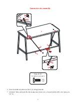
Page 5: ...tructions 6 Stand the unit upright and position at the desired location 7 Attach two Metal Bars E between the Desk Top A and the Bottom Stretcher D with four 5 8 Bolts 1 E A 1 D 1 E E A 5 8 Bolt 4 use...

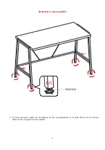
Page 6: ...6 Assembly Instructions 8 If necessary adjust the pre attached floor levelers at the bottom of Side Frames B and C to level the unit B...

Page 7: ...vironment Extreme temperature and humidity changes can cause fading warping shrinking and splitting of wood It is advised to keep furniture away from direct sunlight as sun may damage the finish Prope...

Page 8: ......

Page 9: ...te no retorne est producto a la tienda donde lo compr Por favor llame a nuestro departamento de ayuda al cliente teniendo su instructivo y lista de partes para proveer el modelo nombre de parte o el n...

Page 10: ...todo el material de ferreter a fuera del alcance de ni os 4 Esperar hasta que todos los pasos est n completados antes de apretar los pernos 5 Asegurar de que los pernos est n apretados antes de usar...

Page 11: ...do A Tapa de escritorio Cant 1 B Marco izquierdo Cant 1 C Marco derecho Cant 1 D Soporte inferior Cant 1 E Barra de metal Cant 2 1 Perno de 5 8 Cant 8 1 extra 2 Perno de 2 1 4 Cant 4 1 extra 3 Arandel...

Page 12: ...r la tapa de escritorio A boca abajo en una superficie nivelada y protegida como se muestra 3 Adjuntar el marco izquierdo B a la tapa de escritorio A con 2 pernos de 2 1 4 2 y 2 arandelas 3 y 4 4 Adju...

Page 13: ...ble 6 Poner la unidad en posici n vertical y en el lugar deseado 7 Adjuntar 2 barras de metal E entre la tapa de escritorio A y el soporte inferior D con 4 pernos de 5 8 1 E A 1 D 1 E E A Perno de 5 8...

Page 14: ...6 Instructivo de ensamble 8 Si fuera necesario ajuste los niveladores de piso pre adjuntados en la parte inferior de los marcos laterales B y C para nivelar la unidad B...

Page 15: ...s molduras que se contraigan o que la madera se raje Es recomendable mantener la unidad lejos del sol directo ya que puede da ar el acabado Cuidados adecuados y limpieza pueden extender la vida til de...

Page 16: ......

Reviews: