background image

 20

 21

20 lbs

. / 9.1 kg

.

40 lbs

. / 18.1 kg

.

40 lbs

. / 18.1 kg

.

30 lbs

. / 13.6 kg

.

10 lbs

. / 4.5 kg

.

ADVERTENCIA

: No exceda la capacidad de carga máxima. Superior a la capacidad máxima de carga puede  


               resultar en fracaso y la posibilidad de lesiones.

Instrucciones de cuidado:  

Desempolve con un paño limpio y libre de pelusa.  

Utilice un pulidor en spray para muebles según se 

necesite. 

Servicio al Cliente:

877.436.7290

[email protected]

Su completa satisfacción es nuestra prioridad número 1. Nuestro producto está diseñado y fabricado para cum-

plir con la más alta calidad de las normas. En el caso de que tenga preguntas sobre el ensamblaje, o partes falta 

o está dañado, nuestro departamento de servicio al cliente apreciaría la oportunidad de ayudarle. 

Este producto cuenta con un (1) año de garantía contra defectos de fabricación y de materiales. El producto de-

fectuoso será reemplazado de forma gratuita dentro del periodo de garantía establecido, cuando sea devuelto 

por el comprador original con prueba de compra. Este producto no está garantizado contra el desgaste o ro-

tura debido al mal uso y/o abuso. Por favor, póngase en contacto con nuestro Servicio al Cliente al 1-877-436-

7290 para obtener información sobre la garantía. Esta garantía le otorga derechos legales específicos y usted 

también puede tener otros derechos que varían de estado a estado.

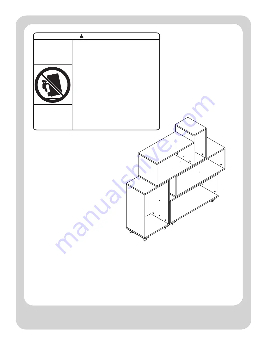
!

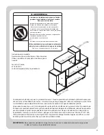
Lesiones por aplastamiento graves o fatales 

pueden ocurrir debido a la caida el mueble.

 Para prevenir la caida:

- Instalar los sujetadores contra caídas proporcionada.

- Coloque los artículos más pesados en las repisas. 
   inferiores o cajones inferiores y lo más atrás posible.
- A menos de que esté especifícamente diseñado para 
   acomodarlo, no coloque televisores u otro objeto pesado 
   sobre este producto.
- Nunca permita que los niños se suban o cuelguen sobre 
   los cajones, puertas o repisas.
- No abrir más de un cajón a la vez.
(O)
- No quitar o eliminar el sistema de bloqueo del cajón.

Utilice sujetadores de pared pueden solamente 

reducir, pero no eliminan los riesgos de caidas.

Esta es una etiqueta permanente. No removerla.

ADVERTENCIA

Summary of Contents for MS16-D4-1007-01

Page 1: ...vice 1 877 436 7290 customersupport tenspringstreet com THIS INSTRUCTION BOOKLET CONTAINS IMPORTANT SAFETY INFORMATION PLEASE READ AND KEEP FOR FUTURE REFERENCE Manufactured By BDDMI 1321 Tyler St NE...

Page 2: ...PANEL M BACK PANEL N SIDE PANEL O TOP PANEL P BOT TOM PANEL Q BACK PANEL R TOP PANEL S BOT TOM PANEL T FOOT X8 L M N O P Q R S T U Before you begin 1 Check for damaged or missing parts 2 Use the cart...

Page 3: ...LIST CAUTION 1 Make sure the screws go through the pre drilled holes properly 2 Do not over tighten bolts 5 Allen Wrench x2 3 Cam B olt x40 4 Cam x40 1 Large Wooden D owel x40 2 Small Wooden D owel x8...

Page 4: ...AUTION 1 Make sure the screws go through the pre drilled holes properly 2 Do not over tighten bolts 11 Washer x2 9 Brown Cam Cover x10 10 White Cam Cover x21 7 Binding B olt x9 8 Black Cam Cover x22 1...

Page 5: ...5 HARDWARE LIST CAUTION 1 Make sure the screws go through the pre drilled holes properly 2 Do not over tighten bolts 15 Wall S crew x1 13 Wall Strap x1 14 Truss Head S crew x1...

Page 6: ...6 1 2 3 4 5 180 HOW TO USE THE CAM LOCK SYSTEM...

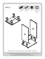
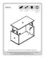
Page 7: ...Leave 1 2 of the dowels sticking out 2 Screw In cam bolts must be screwed down flush 3 Refer to page 6 for instructions on how to use the cam lock system NOT TO SCALE REFER TO PAGE 3 FOR ACTUAL SIZE...

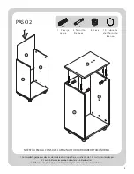
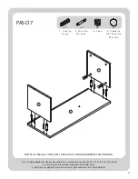
Page 8: ...Leave 1 2 of the dowels sticking out 2 Screw In cam bolts must be screwed down flush 3 Refer to page 6 for instructions on how to use the cam lock system NOT TO SCALE REFER TO PAGE 3 FOR ACTUAL SIZE...

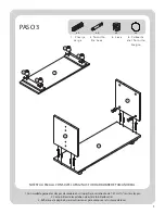
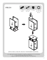
Page 9: ...Leave 1 2 of the dowels sticking out 2 Screw In cam bolts must be screwed down flush 3 Refer to page 6 for instructions on how to use the cam lock system NOT TO SCALE REFER TO PAGE 3 FOR ACTUAL SIZE...

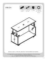
Page 10: ...e Leave 1 2 of the dowels sticking out 2 Screw In cam bolts must be screwed down flush 3 Refer to page 6 for instructions on how to use the cam lock system NOT TO SCALE REFER TO PAGE 3 FOR ACTUAL SIZE...

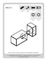
Page 11: ...e Leave 1 2 of the dowels sticking out 2 Screw In cam bolts must be screwed down flush 3 Refer to page 6 for instructions on how to use the cam lock system NOT TO SCALE REFER TO PAGE 3 FOR ACTUAL SIZE...

Page 12: ...e Leave 1 2 of the dowels sticking out 2 Screw In cam bolts must be screwed down flush 3 Refer to page 6 for instructions on how to use the cam lock system NOT TO SCALE REFER TO PAGE 3 FOR ACTUAL SIZE...

Page 13: ...e Leave 1 2 of the dowels sticking out 2 Screw In cam bolts must be screwed down flush 3 Refer to page 6 for instructions on how to use the cam lock system NOT TO SCALE REFER TO PAGE 3 FOR ACTUAL SIZE...

Page 14: ...e Leave 1 2 of the dowels sticking out 2 Screw In cam bolts must be screwed down flush 3 Refer to page 6 for instructions on how to use the cam lock system NOT TO SCALE REFER TO PAGE 3 FOR ACTUAL SIZE...

Page 15: ...Leave 1 2 of the dowels sticking out 2 Screw In cam bolts must be screwed down flush 3 Refer to page 6 for instructions on how to use the cam lock system NOT TO SCALE REFER TO PAGE 3 FOR ACTUAL SIZE...

Page 16: ...Leave 1 2 of the dowels sticking out 2 Make sure the bolts go through the pre drilled holes properly 3 Do not over tighten bolts NOT TO SCALE REFER TO PAGE 3 FOR ACTUAL SIZE HARDWARE 2 Small Wooden D...

Page 17: ...Leave 1 2 of the dowels sticking out 2 Make sure the bolts go through the pre drilled holes properly 3 Do not over tighten bolts NOT TO SCALE REFER TO PAGE 3 FOR ACTUAL SIZE HARDWARE 2 Small Wooden D...

Page 18: ...place Leave 1 2 of the dowels sticking out 2 Make sure the bolts go through the pre drilled holes properly 3 Do not over tighten bolts NOT TO SCALE REFER TO PAGE 3 FOR ACTUAL SIZE HARDWARE 5 Allen Wre...

Page 19: ...Leave 1 2 of the dowels sticking out 2 Make sure the bolts go through the pre drilled holes properly 3 Do not over tighten bolts NOT TO SCALE REFER TO PAGE 3 FOR ACTUAL SIZE HARDWARE 2 Small Wooden D...

Page 20: ...inst wall mark position of strap hole on wall drill 1 4 hole tap in wall anchor fasten anti tip strap with wall screw provided NOT TO SCALE REFER TO PAGE 3 FOR ACTUAL SIZE HARDWARE 14 Truss Head S cre...

Page 21: ...d free of charge within the stated warranty period when returned by the original purchaser with proof of purchase This product is not guaranteed against wear or breakage due to misuse and or abuse Ple...

Page 22: ...7290 customersupport tenspringstreet com ESTE MANUAL DE INSTRUCCIONES CONTIENE INFORMACI N IMPORTANTE DE SEGURIDAD POR FAVOR LEA Y GUARDE PARA REFERENCIA FUTURA Fabricado Por BDDMI 1321 Tyler St NE Mi...

Page 23: ...EL INFERIOR C PANEL SUPERIOR D PANEL POSTERIOR E PANEL LATER AL F PANEL LATER AL G PANEL INFERIOR H PANEL SUPERIOR I PANEL LATER AL J PANEL LATER AL K A B C D E F G H I J K PANEL INFERIOR L PANEL SUPE...

Page 24: ...PRECAUCI N 1 Cerci rese que los tornillos pasen por los agujeros pretaladrados de manera apropiada 2 No sobreapriete los tornillos 5 Llave Allen x2 3 Tor nillo de Leva x40 4 Leva x40 1 Clavija Larga x...

Page 25: ...llos pasen por los agujeros pretaladrados de manera apropiada 2 No sobreapriete los tornillos 11 Arandela x2 9 Cubier ta del Tor nillo M ar r n x10 10 Cubier ta del Tor nillo Blanco x21 7 Tor nillo de...

Page 26: ...FERRETER A PRECAUCI N 1 Cerci rese que los tornillos pasen por los agujeros pretaladrados de manera apropiada 2 No sobreapriete los tornillos 15 Tor nillo de Pared x1 13 Cincha de Pared x1 14 Tor nill...

Page 27: ...6 1 2 3 4 5 180 COMO USAR EL SISTEMA FIJADOR DE LEVA...

Page 28: ...cm en las clavijas 2 Los tornillos de leva deben de estar atornillados al ras 3 Refi rase a la p gina 6 para instrucciones para como usar el sistema de levas NO EST A ESCALA CONSULTE LA P GINA 3 FOR...

Page 29: ...cm en las clavijas 2 Los tornillos de leva deben de estar atornillados al ras 3 Refi rase a la p gina 6 para instrucciones para como usar el sistema de levas NO EST A ESCALA CONSULTE LA P GINA 3 FOR...

Page 30: ...7 cm en las clavijas 2 Los tornillos de leva deben de estar atornillados al ras 3 Refi rase a la p gina 6 para instrucciones para como usar el sistema de levas NO EST A ESCALA CONSULTE LA P GINA 3 FOR...

Page 31: ...7 cm en las clavijas 2 Los tornillos de leva deben de estar atornillados al ras 3 Refi rase a la p gina 6 para instrucciones para como usar el sistema de levas NO EST A ESCALA CONSULTE LA P GINA 3 FOR...

Page 32: ...7 cm en las clavijas 2 Los tornillos de leva deben de estar atornillados al ras 3 Refi rase a la p gina 6 para instrucciones para como usar el sistema de levas NO EST A ESCALA CONSULTE LA P GINA 3 FOR...

Page 33: ...7 cm en las clavijas 2 Los tornillos de leva deben de estar atornillados al ras 3 Refi rase a la p gina 6 para instrucciones para como usar el sistema de levas NO EST A ESCALA CONSULTE LA P GINA 3 FOR...

Page 34: ...cm en las clavijas 2 Los tornillos de leva deben de estar atornillados al ras 3 Refi rase a la p gina 6 para instrucciones para como usar el sistema de levas NO EST A ESCALA CONSULTE LA P GINA 3 FOR...

Page 35: ...cm en las clavijas 2 Los tornillos de leva deben de estar atornillados al ras 3 Refi rase a la p gina 6 para instrucciones para como usar el sistema de levas NO EST A ESCALA CONSULTE LA P GINA 3 FOR...

Page 36: ...cm en las clavijas 2 Los tornillos de leva deben de estar atornillados al ras 3 Refi rase a la p gina 6 para instrucciones para como usar el sistema de levas NO EST A ESCALA CONSULTE LA P GINA 3 FOR...

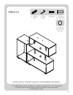
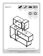
Page 37: ...as clavijas 2 Cerci rese que los pernos pasen por los agujeros pretaladrados de manera apropiada 3 No sobreapriete los pernos NO EST A ESCALA CONSULTE LA P GINA 3 FOR HARDWARE DE TAMA O REAL 2 Clavija...

Page 38: ...as clavijas 2 Cerci rese que los pernos pasen por los agujeros pretaladrados de manera apropiada 3 No sobreapriete los pernos NO EST A ESCALA CONSULTE LA P GINA 3 FOR HARDWARE DE TAMA O REAL 2 Clavija...

Page 39: ...1 27 cm en las clavijas 2 Cerci rese que los pernos pasen por los agujeros pretaladrados de manera apropiada 3 No sobreapriete los pernos NO EST A ESCALA CONSULTE LA P GINA 3 FOR HARDWARE DE TAMA O RE...

Page 40: ...as clavijas 2 Cerci rese que los pernos pasen por los agujeros pretaladrados de manera apropiada 3 No sobreapriete los pernos NO EST A ESCALA CONSULTE LA P GINA 3 FOR HARDWARE DE TAMA O REAL 2 Clavija...

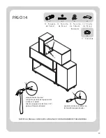
Page 41: ...ha en la pared taladre un agujero de 6 35 mm 1 4 golpee el taquete de pared apriete la cincha anti caidas con los tornillos proporcionados NO EST A ESCALA CONSULTE LA P GINA 3 FOR HARDWARE DE TAMA O R...

Page 42: ...nt a establecido cuando sea devuelto por el comprador original con prueba de compra Este producto no est garantizado contra el desgaste o ro tura debido al mal uso y o abuso Por favor p ngase en conta...

Reviews: