


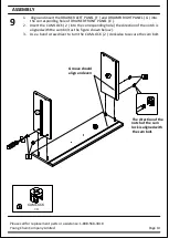


9
Page 14
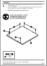
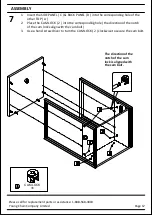
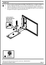
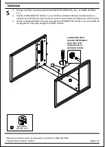
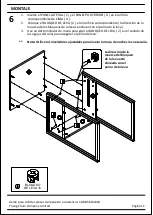
1. Align and insert the DRAWER LEFT PANEL ( F ) and DRAWER RIGHT PANEL ( G ) into
the corresponding hole of DRAWER FRONT PANEL ( E ).
2. Insert the CAM LOCK ( 2 ) into the corresponding hole ( the direction of the notch is
aligned with the cam bolt as the figure shown below ).
3. Use a hand screwdriver to turn the CAM LOCK ( 2 ) clockwise to secure the cam bolt.
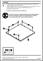
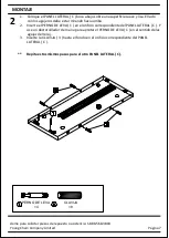
ASSEMBLY
Please call for replacement parts or assistance: 1-888-568-3818
Young Chain Company Limited
G
CAM LOCK
×4
2
Groove should
align and even
The direction of the
notch of the cam
lock is aligned with
the cam bolt.